Posts

Showing posts from May, 2011

Running LED with 4017

Image
Running LED with 4017 complete with PCB layout. The series of 8 LED current is the basis for creating an 8-point LED. Slightly different from the running LED with IC 4017 (decade counter), 8 running this led is lit in sequence, but that has been previously flame does not die when the led is lit afterwards. 8 led to death after led to the fire-8. Meanwhile in the running LED (decade counter), the system LED lights like "point", there is only one LED that flashes between the tenth led. The main component is the IC 74LS164 (SHIFT REGISTER), with its timer is astable multivibrator circuit (using IC NE555). The series will be more efficient when using a stable power supply (regulator) using IC Regulator 7805. Under this scheme a series of stable power supply 5 volts dc.

Make a series letters from the LED

Image
Make a series letters from the LED , Things to consider before making the sign of the LED array, 1) Use LED nodes. 2) Paint the top of the PCB with a dark color (black). 3) Note the LED specifications. In this experiment use a 5mm diameter LED nodes that emit red, specification voltage of 3 volts. The assembly of LED: 1) One letter composed at most 5 columns and 7 rows. 2) One column mostly composed by 6 LEDs are arranged series. 3) Then the fifth column are connected in parallel. 4) Each column given the constraints, Rx, which amount depends on the number of LEDs in one column and depends also on the type of LED (in this experiment that used LED 5mm in diameter, clear with red light beam). 5) In a column consisting of 6 LEDs, Rx = 330 ohm, 5 LEDs, Rx = 560 Ohms, 4 LEDs, Rx = 680 Ohms Remember, this provision applies to 5 mm LED red light beam nodes. 6) Every letter was given FCS9013 transistor amplifier. Here is one letter LED scheme. Medium picture below is the lay out of the 2-lette

Subwoofer power amplifier IC OPA541BM

Image
Subwoofer power amplifier circuit based on IC OPA541BM very suitable for use in subwoofer speakers, these amplifiers possess excellence in sound issued because the sound is very clear and issued in accordance with subwoofer speakers in a low tone. Subwoofer power amplifier IC OPA541BM Circuit

120W amplifier with LM12

Image
This is power amplifier with basic amplifiy on IC LM12.

BTL Stereo Amplifier TDA7052 / 3

Image
This is BTL stereo power amplifier with basic amplifier on IC TDA7052 / TDA7053

Condenser Pre Amplifier LM 1458

Image
This is a simple preamplifier circuit for electret condenser microphone. using a LM1458 dual op amp IC. The circuit takes the audio signal rom the condenser microphone and amplifier it, so you can use the microphone as the input to some device which wouldn’t normally accept microphone level signals . Schematic Circuit of Microphone Electret Condenser Pre Amplifier The circuit requires a 6-9 volt supply. Output of the microphone amplifier can be made variable by connecting a 10kΩ potentiometer . Circuit’s gain can be increased by men perbesar the value of 47K, depending on the input sensitivity of the main amplifier system. The microphone should be housed in a small round enclosure. List componet of condenser pre-amp mic circuit Q1,Q2    : LM1458 Op-Amp R1,R2,R3 : 4.7k ohm resistor R4, R5   : 10k ohm resistor R6,R7    : 47k ohm resistor C1,      : 0.22uF ceramic capacitor C2       : 1uF ceramic capacitor Absolute maximum ratings of LM 1458 IC Supply Voltage               :  ±18V Power D

Power Supply Variable 1.3V - 12.2V 1A Circuit

Image
Power supply circuit to generate output below were variations between 1.3V DC to 12.2V DC with 1A current. In addition, the power supply circuit is also equipped with over-current protection or shield against belebih flow. Power supply circuit is very simple, but the quality is quite good, made her basiskan regulator IC LM723 is a pretty legendary. Description: R2 to set the output voltage. The maximum current is determined by R3, over-current protection circuit inside the LM723 to detect the voltage on R3, if it reaches 0.65 V, the voltage output will be off her. So the current through R3 can not exceed 0.65 / R3 although output short-circuit in his. C3 and C4 are ceramic capacitors, as much as possible directly soldered to the PCB, this is because the LM723 is prone to oscillation that is not cool. LM723 works with 9.5V input voltage to 40 V DC and the LM723 can generate its own current of 150mA when the output voltage is not more than 6-7V under input voltage. Specifications: Output

TDA2005 2 X 20 Watt Power Amplifier

Image
This time, there is a series of audio amplifer 20W as well, but using IC TDA 2005 as a series of his base amplifier. The series of 2x20 Watt Audio Power Amplifier using TDA2005 can you see in the picture below. Technical Data: Performance of TDA2005M: (for this circuit); At 4.14 V supply voltage: 2 x 20 watts (stereo) into 4 Ohms. Distortion: Approx. 0.2% at 4 Watts into 4 ohm load. Frequency Range: Approx. 20 Hz to 22 KHz. Input Sensitivity: Approx. maximum 150 mV rms. . Power supply: + 8 to 18 volts, approx. 3.5 Amps maximum per channel.

Toggle switch with Infra Red IR

Image
Toggle switch in this article is a series of toggle switches that are controlled by infrared light. The series toggle switch is made from a combination of data flip-flop CD4013 2 units. Receiver circuit of the infrared light signals arranged with infrared receiver as found on television remote receiver. Infrared signal from remote is used as clock signals and data to the data flip-flop first. then the second flip-flop data set as a toggle flip-flop toggle the output signal is used to drive the relay. for more details can be seen in thethe following image . Series Toggle Switch With Infra Red (IR) that is required to supply voltage range of 12VDC and the output of Toggle Switch With Infra Red (IR) is dapt used to turn on the lights or other electronic devices with DC or AC voltage source. Series Toggle Switch With Infra Red (IR) was isolated from the load that is placed for use as the final relay.

Mini Amplifier with 3 Transistor

Image
Mini 3 transistor amplifier is a simple amplifier with 50mW power drawn by 3 transitor. The series of three mini-amplifier transistors can be used for loud speaker 8 ohm load. Source voltage required to activate the mini-amplifier can be drawn from the batteries 9V.Rangkaian 3 transistor amplifier is often used in simple portabe audio devices such as radios or small tape recorder. Mini-transistor amplifier circuit 3 is quite simple as shown in the figure below. Mini-transistor amplifier circuit 3 includes type of amplifier OTL (Output Transformer Less). Mini-transistor amplifier circuit 3 is used for output coupling capacitors. Amplifier circuit is simple and suitable when used for audio amplifier experiment.

6 to 12 Volt Power Supply Inverter

Image
This inverter circuit can provide up to 800mA of 12V power from a 6V supply. For example, you could run 12V car accessories in a 6V (British?) car. The circuit is simple, about 75% efficient and quite useful. By changing just a few components, you can also modify it for different voltages. Part List: R1, R4 2.2K 1/4W Resistor R2, R3 4.7K 1/4W Resistor R5 1K 1/4W Resistor R6 1.5K 1/4W Resistor R7 33K 1/4W Resistor R8 10K 1/4W Resistor C1,C2 0.1uF Ceramic Disc Capacitor C3 470uF 25V Electrolytic Capcitor D1 1N914 Diode D2 1N4004 Diode D3 12V 400mW Zener Diode Q1, Q2, Q4 BC547 NPN Transistor Q3 BD679 NPN Transistor L1 See Notes MISC Heatsink For Q3, Binding Posts (For Input/Output), Wire, Board source: LINK

5 Volt Switching Regulator Power Supply

Image
The switching regulator power supply used LM2575-5.0 on this schematic. You can make the stable voltage by using the 3 terminal regulator like LM317. However, because the output electric current and the inputted electric current are the same approximately, the difference between the input electric power (The input voltage x The input electric current) and the output power (The output voltage x The output current) is consumed as the heat with the regulator. Because it is, the efficiency isn�t good. Data sheet for LM2575 SIMPLE SWITCHER 1A Step-Down Voltage Regulator http://www.national.com/pf/LM/LM2575.htm

150 watts power amplifier circuit

Image
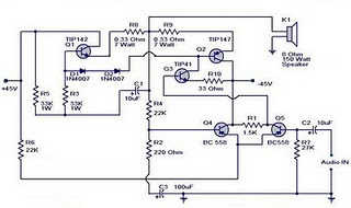
Amplifier circuit is 150 watts power amplifier circuit is quite simple. This circuit requires only 5 pieces of transistors as the main component of reinforcement. There is no equalizer option on this amplifier circuit because it can be said of this series is very simple, so do not you compare it with that sold in the market which are usually equipped with various sound system and equalizer settings.  But to add to your collection circuit, this circuit is fairly easy and inexpensive to make and maybe one day you may need as a weak signal booster from your electronic circuit. Or you can also make this amplifier as an amplifier of high frequency signal from the output circuit animal repellent and I guarantee the results are very satisfactory. Power supply required is two-polarity power supply is + - 45 volts. Maximum power that can be obtained by this amplifier circuit is around 150 watts. As the volume control you can add potensio or variable resistor 10 Kohm in series at the input. Use

Altium Designer 10.0 – Free Download

Image
A unified electronic product development solution Altium Designer is the world’s first and only unified electronic product development system that allows engineers to take a design from concept to completion within a single application. Don’t limit your design horizons. Get yourself out of the traditional design box and into holistic design. Use all the available technologies and devices to bring your ideas to life and turn them into the smart, connected products that we’ll all be using tomorrow. Altium Designer 10.0 That’s what Altium Designer is all about – freeing you from the constraints of traditional design limitations and the old “divide and conquer” approach. Altium Designer provides one single unified solution for the entire design process. It allows you to explore and do more, do it in new ways, and design things that haven’t even been thought of yet. Think and design beyond the confines of the device itself and start designing your customer’s total product experience. That’s

Measure your stress level – Tension meter

Image
If you, like so many other people in this day and age, arrive home from work stressed out and with the problems of the day still lingering,this simple little instrument will go a long way to relieving nervous tension. Of the various types of feedback devices, probably the best approach for the amateur experimenter is the Galvanograph, better known as the Galvanic Skin Response Monitor. The instrument described here relies for its operation on changes in skin resistance in sympathy with changes in emotional state. An increase in tension level reduces skin resistance and, conversely, a decrease in tension is accompanied by an increase in skin resistance. The correlation between emotional stress and skin resistance is still not fully understood. What is known, though, is that minute changes in the permeability of the skin produce corresponding voltage variations across two electrode pads attached to two fingers on the same hand. Tension Monitor meter circuit These signal fluctuations are

Smart Tracker - track anything from your child to shoes

The EPE Minder consists of two type- approved transmitter units and a receiver. If either transmitter becomes separated from the receiver, a buzzer in the latter part will sound. The receiver is fitted with a switch to allow the use of only one transmitter if required. MIND HOW YOU GO This system was originally designed as a two-channel child alarm (to protect either a single child or two children at the same time) but many other applications spring to mind. For example, one transmitter could be placed inside a briefcase and another in a coat pocket. If the user forgot to pick up either of these items and walked away, the buzzer would sound in the receiver. The receiver must be carried on the per- son in a way that would make it practically impossible to lose it. This could be done using a belt clip, for example. Note that it will not be possible to use this system if either the transmitter or receiver were placed inside metal containers or if there were substantial metallic “screening

Power Supply Variable 1.3V - 12.2V 1A Circuit

Image
Power supply circuit to generate output below were variations between 1.3V DC to 12.2V DC with 1A current. In addition, the power supply circuit is also equipped with over-current protection or shield against belebih flow. Power supply circuit is very simple, but the quality is quite good, made her basiskan regulator IC LM723 is a pretty legendary. Description: R2 to set the output voltage. The maximum current is determined by R3, over-current protection circuit inside the LM723 to detect the voltage on R3, if it reaches 0.65 V, the voltage output will be off her. So the current through R3 can not exceed 0.65 / R3 although output short-circuit in his. C3 and C4 are ceramic capacitors, as much as possible directly soldered to the PCB, this is because the LM723 is prone to oscillation that is not cool. LM723 works with 9.5V input voltage to 40 V DC and the LM723 can generate its own current of 150mA when the output voltage is not more than 6-7V under input voltage. Specifications: Output

LM4651 and LM4652 170W power amplifier

Image
170 Watt power amplifier is a power amplifier that is built by IC LM4651 and LM4652. Part of this power amplifier driver using the LM4651 IC designed specifically for the purpose of the class AB amplifier driver with short circuit protection feature, containing under voltage, thermal shutdown protection and standby functions. Section 170 Watt power amplifier using LM4651 IC with a MOSFET power amplifier is equipped with temperature sensors that will be used by IC LM4651 as controlnya thermal signal. IC IC LM4651 and LM4652 are designed specifically to each other in pairs to create a class AB power amplifier with protection features are detailed. Detailed series of 170 Watt power amplifier can be seen in thethe following figure . Power amplifier circuit requires supply voltages +22 V DC symmetrical 0-22V. Power Amplifier with IC LM4651 and LM4652 are often used in portable HiFi systems such as powered speakers, power subwoofer and car audio power Booter. D1, D2, D3 and D4 in series 170

170W power amplifier LM4651 and LM4652

Image
170 Watt power amplifier is a power amplifier that is built by IC LM4651 and LM4652. Part of this power amplifier driver using the LM4651 IC designed specifically for the purpose of the class AB amplifier driver with short circuit protection feature, containing under voltage, thermal shutdown protection and standby functions. Section 170 Watt power amplifier using LM4651 IC with a MOSFET power amplifier is equipped with temperature sensors that will be used by IC LM4651 as controlnya thermal signal. IC IC LM4651 and LM4652 are designed specifically to each other in pairs to create a class AB power amplifier with protection features are detailed. Detailed series of 170 Watt power amplifier can be seen in thethe following figure . Power amplifier circuit requires supply voltages +22 V DC symmetrical 0-22V. Power Amplifier with IC LM4651 and LM4652 are often used in portable HiFi systems such as powered speakers, power subwoofer and car audio power Booter. D1, D2, D3 and D4 in series 170

Tube Power Amplifier 35W Push Pull

Image
Tube Power Amplifier 35W Push Pull is made using a tube and eventually compiled configuration push-pull amplifier. Tube Power Amplifier 35W Push Pull tube til it using EL-34 as the amplifier end. In the power amplifier that is made with a tube at a glance looks simple because the use of active components that are not complex. It should be noted that the use of tubes in Tube Power Amplifier 35W Push Pull require a high voltage supply, therefore in the process of making and finishing must be careful of high voltage and radiation. Detailed series of Tube Power Amplifier 35W Push Pull can be seen in the following figure. Tube Power Amplifier Series 35W Push Pull Sign Components Tube Power Amplifier 35W Push Pull R1 = 470K 0.5 W R2-5 = 2K2 0.5W R3 = 150K 0.5W R4 = 220K 0.5W R6-10 = 56K 0.5W R7 = 3.9K 0.5W R8 = 220R 0.5W R9 = 1M 0.5W R11 = 39K 1W R12-23 = 180K 0.5W R13-21 = 820K 0.5W R14-22 = 5K6 0.5W R15-20 = 680K 0.5W R16-19 = 100K 0.5W R17-18 = 3K3 1W R24 = 470R 2W TR1-2 = 470R 1W Variabl

Rangkaian Power Supply for tube amplifier

Image
Power supply for EL-34 tube is specially designed for the purposes of power supply at the push-pull amplifier with EL-34 tube as in article 35 Watt Tube Power Amplifier Push Pull before. Power supply for EL-34 tube amplifier is made with transformers CT and 2 pieces diode as rectifier. Mechanical filters are applied in the power supply uses 3 levels. Power supply for tube power amplifier can deliver output voltages +220 VDC. Circuit details can be seen in the following figure. The above power supply circuit has a high output voltage so that need to be considered in the manufacture and perakitanya because electricity can tesengat (stun). Power Supply For Tube Power Amplifier With Diode EL-34 was created specifically for the power amplifier tube push pull EL-34.

Class A headphone amplifier

Image
Class A headphone amplifier Class A headphone amplifier

Turbo Bass Circuit

Image
Turbo Bass Circuit Turbo Bass Circuit

HiFi Headphone amplifier

Image
HiFi Headphone amplifier HiFi Headphone amplifier

TDA1308T Headphone amplifier circuit

Image
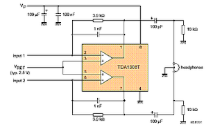
TDA1308T Headphone amplifier circuit  TDA1308T Headphone amplifier circuit

Headphone amplifier circuit

Image
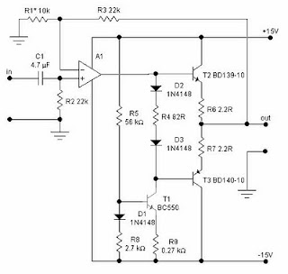
Headphone amplifier circuit with op amp ic OPA134, 2134, NE5532, 5534. Headphone amplifier circuit with op amp

Hi-Fi 25W Power Amplifier (Class-A)

Image
Hi-Fi 25W Power Amplifier (Class-A) Schematics Circuit Click to view larger

Flash Lights with HT2014L

Image
Flash Lights with HT2014L This scheme is almost the same with a flash light with LM3909. In this scheme only requires IC HT2014L as a leader, and a resistor and LED. For voltage here need ration power around 4.5 V. You can apply this series to a wider scale in comparing the use IC LM3909. For the scheme are below:

1.3V DC to 12.2V DC Regulator Power Supply

Image
Power supply circuit to generate output below were variations between 1.3V DC to 12.2V DC with 1A current. In addition, the power supply circuit is also equipped with over-current protection or shield against belebih flow. Power supply circuit is very simple, but the quality is quite good, made her basiskan regulator IC LM723 is a pretty legendary. Description: R2 to set the output voltage. The maximum current is determined by R3, over-current protection circuit inside the LM723 to detect the voltage on R3, if it reaches 0.65 V, the voltage output will be off her. So the current through R3 can not exceed 0.65 / R3 although output short-circuit in his. C3 and C4 are ceramic capacitors, as much as possible directly soldered to the PCB, this is because the LM723 is prone to oscillation that is not cool. LM723 works with 9.5V input voltage to 40 V DC and the LM723 can generate its own current of 150mA when the output voltage is not more than 6-7V under input voltage. Specifications: Output

Transceiver Homebrew QRP SSB 80M Band

Image
Radio communication transceiver is a radio transmitter at the same time the plane doubles as a radio receiver used for communication purposes. It consists of the transmitter and the receiver are assembled in an integrated way. In mulamula generation, the transmitter or receiver or transmitter and receiver sections are assembled separately and is part of a stand sendirisendiri and can work well sendirisendiri Currently employed both parts are integrated in turn. Aircraft simple transmitter consists of an oscillator generating radio vibration and this vibration after vibration boarded with our voice, in a technique called dimodulir radio, then by the antenna is converted into radio waves and transmitted. As we know that the sound waves we can not reach long distances, although its power is quite large, while the radio waves with a relatively small force can reach a distance of thousands of kilometers. In order for our voice can reach a far distance, then our voice superimposed on radio w

Toggle Switch with IR

Image
Toggle switch in this article is a series of toggle switches that are controlled by infrared light. The series toggle switch is made from a combination of data flip-flop CD4013 2 units. Receiver circuit of the infrared light signals arranged with infrared receiver as found on television remote receiver. Infrared signal from remote is used as clock signals and data to the data flip-flop first. then the second flip-flop data set as a toggle flip-flop toggle the output signal is used to drive the relay. for more details can be seen in thethe following image . Series Toggle Switch With Infra Red (IR) that is required to supply voltage range of 12VDC and the output of Toggle Switch With Infra Red (IR) is dapt used to turn on the lights or other electronic devices with DC or AC voltage source. Series Toggle Switch With Infra Red (IR) was isolated from the load that is placed for use as the final relay. source [ link ] 

8 Relay Control Circuit

Image
8 Relay Control Circuit R1-8=4.7 Kohms T1-8= BD139 (R1-8=15 Kohms if T1-8=BD679) RL1-8=6V-24V dc Relay D1-8=1N4148  

TDA7294 150 W Power Amplifier

Image
This is power amplifier based on IC TDA7294 with output power 150W with 8 ohm impedance, source voltage + - 25V. for circuit see image below. TDA7294 Power Amplifier

Mosfet Amplifier with power output 400W

Image
See figure below its power amplifier using transistor mosfet as amplifier. Mosfet Amplifier with power output 400W

230Volt LED Circuit

Image
This is a circuit that is used to menhidupkan LED with voltage 230Volt, 230Volt it so that the voltage must be lowered in accordance with the needs of the LED itself. To lower it even necessary circuit as below.

10Mhz to 1 MHz Frequency Converter

Image
10Mhz to 1 MHz Frequency Converter Circuit Part ListIC1 7404 = 1 IC2 7490A = 1 R 1 K = 2 R 3.3 K = 1 C Trim Polymer 39 pF = 1 C Electrophoresis 4.7 uF 16V = 1 C Milar 47 nF 16 V = 1 C Milar 10 nF 16 V = 1 C Ceramic 68 pF 50 V = 1 

Control Relay Circuit with 9 Second

Image
See figure below its Control Relay Circuit Schematics.

6 to 12 Volt Converter

Image
Below its a converter circuit voltage from 6 Volt to 12 Volt DC. 6 Volt to 12 Volt DC Part List : R1, R4 2 .2K 1/4W Resistor R2, R3 4.7K 1/4W Resistor R5 1K 1/4W Resistor R6 1.5K 1/4W Resistor R7 33K 1/4W Resistor R8 10K 1/4W Resistor C1,C2 0.1uF Ceramic Disc Capacitor C3 470uF 25V Electrolytic Capcitor D1 1N914 Diode D2 1N4004 Diode D3 12V 400mW Zener Diode Q1, Q2, Q4 BC547 NPN Transistor Q3 BD679 NPN Transistor L1 See Notes Notes 1. L1 is a custom inductor wound with about 80 turns of 0.5mm magnet wire around a toroidal core with a 40mm outside diameter. 2. Different values of D3 can be used to get different output voltages from about 0.6V to around 30V. Note that at higher voltages the circuit might not perform as well and may not produce as much current. You may also need to use a larger C3 for higher voltages and/or higher currents. 3. You can use a larger value for C3 to provide better filtering. 4. The circuit will require about 2A from the 6V supply to provide the full 800mA at

230 - 400 Watt Power Amplifier MOSFET

Image
Amplifier circuit below is a series of amplifiers with the amplifier transistor and mosfet. This amplifier output power ranging from 230W up to 400W. 230 - 400 Watt Power Amplifier

800W Power Amplifier MOSFET

Image
This Figure is a schematic power amplifier with power 800 Watt and driver and booster using MOSFET. Audio Power Amplifier with power output 800W

1.3 - 12.2 VDC Variable Power Supply

Image
Power supply circuit to generate output below were variations between 1.3V DC to 12.2V DC with 1A current. In addition, the power supply circuit is also equipped with over-current protection or shield against belebih flow. Power supply circuit is very simple, but the quality is quite good, made ​​her basiccally regulator IC LM723 is a fairly legendary.

System circuit (not) Minimum (Evaluation Board) AT89C2051 and AT89C4051

Image
Maybe we are more familiar with the term Minimum System AT89C2051 circuit, but this time I present a circuit which is not only a series of Minimum System AT89C2051 but more than that. The circuit is more deserves to be called Evaluation Board AT89C2051 and AT89C4051. Some of the advantages of circuit Minimum System AT89C2051 / AT89C2051 and AT89C4051 Evaluation Board which I was present this time, hardware-hardware support below: RS-232 interface, DB-9 Header for LCD display I2C, PCF8574 I / O extender AT24C04, I2C EEPROM

200W power amplifier complete power supply

Image
This 200W power amplifier circuit using IC STK 4050. STK 4050 is a power amplifier module is very powerful, because the IC is already a module then only needed a little extra components to build a reliable 200W Power Amplifier. Here is a picture series of Power Amplifier ICs 200W use STK 4050 complete with its power supply:

Simple Inverter with Two Transistors

Image
The series below is a simple inverter circuit that will change the voltage of 12v dc to 220v ac, with use drive transistor 32 as its tip. Inverter circuit is very simple and easy to assemble and is perfect for just starting to learn to assemble electronic circuits, you can use the transformer 2A to produce about 20 watts output. Do not forget to install coolers in its transistors. good luck.

Improving Performance Bass Amplifier

Image
Stereo power amplifier is less in the bass tones, but if a speaker that sounds just feels solid bass sound, there are several possibilities, the first one speaker cable upside down, try alternating bass and tone tests. If still, you need to use 2 power supply or attempting to use this circuit. Note this circuit works for a power amp that is less power transformer with 2 speakers (stereo). One of the speaker cable (output) should be reversed, this is okay, just a game to lighten the work phase transformer from the blow bass. We recommend that before you try this circuit, turn one speaker cable and a second test speakers with bass tones, the bass should be mutually reduce (bass-bass = 0). Next remove the driver from boknya and turn the speakers (the speaker drivers facing into the wall), the bass should grow (bass + bass = 2bass). One record store in the town of Indramayu is taking this simple way, certainly looks magnet speakers, great. The heart of this circuit using IC with 2 op-am