Posts

Showing posts from April, 2012

Mini and simple power amplifier

Image
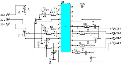
What is the meaning of the picture above? The above picture is a miniature audio amplifier and very simple. Here I will give an audio amplifier schematic is very simple which only requires a few components only, can be seen under this scheme. See from above scheme may occur to you, certainly cheap enough to make this amplifier and quite easy to make. The above simple audio amplifier circuit using an IC as the main amplifier and accompanied by other components. IC used is S1513, which requires a supply voltage ranging from 1.5 volts to 6 volts. And only 0.1 W output power with 4 ohm impedance. For a list components can be seen below. Part list C1 = 100nF C2 = 100uF C3 = 3n3F C4 = 1uF C5 = 1uF U1 = S1513

6 - 12 Volt audio amplifier

Image
The above is an amplifier circuit using supply voltages from 6 volts DC to 12 Volt DC. Power output of the amplifier is quite low with only 1 Watt 8 ohm impedance. You can apply this to the audio signal amplifiers that require strengthening are not so large as in the pocket radio. Part List : R1 =  100K R2 = 39R R3 = 100R C1 = 100nF C2 = 100uF C3 = 100uF C4 = 100uF C5 = 470uF C6 = 100nF C7 = 68pF C8 = 1nF C9 = 47uF IC = SFC2790C

50W car audio amplifier schematic

Image
Car power amplifier uses SI1050GL IC as the main amplifier. The output power 50 Watt 8 ohm mono impedance. Up to 25 Volt DC voltage. with source voltage of this amplifier car battery has to work. Minimum of 12 Volt battery voltage, less than a sound or audio is issued less than the maximum and less good. You can assemble  this circuit amplifier with a schema like this. Part List R1 = 100K R2 = 1R C1 = 2.2uF C2 = 22uF C3 = 100uF C4 = 0.1uF C5 = 100uF U1 = SI1050GL If you want to make stereo amplifier , you must required multiply the two of components. 

450W Power amplifier

Image
Below it is a circuit of power amplifiers with power output of 450 watts mono , amplifiers are also frequently used in the amplifier a high-power amplifier, which used in an event, in the field and the placed closed. Because this amplifier suitable for the woofer, fullrange speaker, and can also be fixed for the subwoofer speaker.  To further strengthen and maximize the amplifier ,its power supply circuit also must be accurate, for electrolytic capacitors in power supply ,voltage capacitors use 80V or more, and a capcity 20000uF upwards, so when the bass amplifier is high , the voltage is not lot of experience dropping. Diode bridge use a minimum of 35A, or adjust the current input voltage. If the power supply has fulfilled the desire, the supply to the power amplifier.

10W audio power amplifier with bass boost

Image
As the amplifier circuit also uses a number of frequencies to drive the loudspeaker, the bass frequencies will be reduced. Therefore need to be plugged the bass-boost control at fedback loop amplifier, this is done to overcome the decline in quality. Graph bass can reach a maximum at +16.4 dB @ 50Hz. This circuit can be connected directly to the CD player, tuner, and tape recorders. Q3 and Q4 must be in pairs with a heatsink. Adjust the volume control at minimum position and R3 with a minimum value of resistance as well. try enabling circuit R3 da set up to read the flow of about 20 to 25mA. Wait for 15 minutes, connect the ground at J1, P1, C2, C4 C3dan. Connect also C9 at the output ground. For his series of power supply you can use the following scheme that fits perfectly with this amplifier.

Power amplifier for TV audio

Image
In this amplifier circuit using IC TDA8944J as the main amplifier with dual-channel audio amplifier with 2 x 7W output power at 8 Ω impedance. And a minimum supply voltage of 9-18 Volts. In this ic contains two Bridge Tied Load or BTL amplifier. The circuit is often found in audio amplifier in a series of television, besides TDA2003, TDA2006 and so forth. PCB for a series of amplifiers using IC TDA8944J is very compatible with all other types of IC in IC TDA894X family unit , and below is a schematics.

300W Subwoofer Power Amplifier

Image
This is an amplifier circuit that is formed from a transistor amplifier miraculous. This circuit is used in the speaker subwoofer with 300W maximum power on each side. To apply it, can be used in the room that is not too large, like the car. And the voltage needed between 25 to 42 Volt DC. This is schematic of 300W subwoofer amplifier

Simple FM transmitter with 2N3904

Image
In this section discuss about the series of mini fm transmitter, with broadcast coverage of about 300-400 meters. when using a 9 volt working voltage, the transmit power of about 300 meters and when using the working voltage 12 volts, the range of about 400-450 meters, depending on the antenna you use. This scheme of simple fm transmitter For L1 and L2 windings 5 times the wrap, you can use a pen to fill melilitnya so neat and after lepaslah content of these pens. C5 is used for placement of broadcasting frequencies, can be tuned between 88-108 mhz, to reach further use steering antenna or Yagi antenna. Part List C1 = 0.001uF C2 = 5.6pF C3 = 10uF C4 = 10uF C5 = 3 - 18pF Adjustable capacitor R1 = 270R R2 = 4.7K R3 = 10K R4 = 100K R5 = 4.7K R6 = 4.7K Q1 = 2N2222A Q2 = 2N3904 L1 = 5 turn L2 = 5 turn

45 W Stereo Tube Amplifier

Image
Stereo Amplifier with Tube Stereo amplifier is very simple, consisting of 5 active components including the power supply it. Series Stereo Amplifier With Tube was prepared with 5 units trioda tube consisting of 1 unit tubes 5Y3 GT vacuum rectifier, 2 tube tube trioda 6SF5 GT high-mu tube 6k6 and 2 units which form the power beam amplifiers. Power consumption for the circuit with a tube stereo amplifier is not more than 45 Watt. Current consumption for the circuit with a tube stereo amplifier is around 3A. A complete range of stereo amplifiers with this tube can be seen from the following series of images. Stereo Amplifier With Tube Sign Component Stereo Amplifier With Tube R1, R10, R13 2.2M R2 470K 1/2W 1 Meg 1/2W R3 R4 220K 1/2W R5 330 Ohm 2W R6 220K 1/2W R7 2.2Meg 1/2W R8 1Meg 1/2W R9 720 Ohm 20W R11 33K 1/2W R12 22K 1/2W C1, C9 400V 0.005uF C2 0.05uF 600V C3 20uF 25V C4 0.01uF 400V C5 200uuF 400V C6, C7 15uF 450V C8 15uF 400V T1 117V Primar

LM317 Simple Audio Amplifier

Image
You most likely know that LM317 IC is applied as an practical provide regulator, but did you know it can be applied as an audio amplifier? This is a Low power Amplifier LM317 Simple Audio Amplifier Circuit a audio  designed with LM317 that offers a optimum probable 1W audio strength.  LM317 Simple Audio Amplifier Circuit Diagrams : LM317 Simple Audio Amplifier Circuits Utilization a amazing heatsink for the LM317 IC and modify the 5K various resistor so that you have 4.5V on 10Ω resistor (or LM317 pin 2, Vout).

1500W Stereo Power Amplifier Schematic

Image
Circuit Power Amplifier has a power output of up to 1500W RMS power amplifier circuit is often used to power sound systems keperlun for outdor. In the final image can be seen a series of power amplifiers using 10 sets of power transistors for the ending. This power amplifier circuit using a transistor amplifier from the front, signal splitter, driver and power amplifier. Current consumption required is quite large power amplifier that is 15-20 A 1500W power amplifier circuits for this. Supply voltage needed by the power of this amplifier is the optimal working order symmetrical 130VDC (130VDC-130VDC ground). 1500W amplifier circuit below is a picture series of mono, stereo if you want to make it necessary to make two copies of the circuit. For more details can be viewed directly image the following 1500W power amplifier circuit. The series of High Power Amplifier 1500W With Transistor Click Image to view larger In the above series of power amplifer 1500W is equipped

RF Amplifier circuit with 2SC1970 2N4427

Image
RF power amplifier circuit of this work is based on the transistor 2SC1970 and 2N4427. The set output power of 88-108 MHz FM RF Amplifier With 2SC1970 is about 1.3W and the input driver is 30-50mW. RF driver amplifier circuit uses a 2N4427 and its power amplifier using a transistor 2SC1970. At the time of the amplifier circuit tuning FM 88-108 MHz RF Amplifier With 2SC1970 should use the power meter / watt meter or SWR or RF field can also use the meter. RF amplifier circuit can work from the frequency of 88-108 MHz. RF Amplifier Circuit of 88-108 MHz FM RF Amplifier With RF 2SC1970 can radiate far enough. At the time of tuning you should use a 50 Ohm dummy load. For the input signal should be installed to regulate the VR level so as not to over-modulation (30-50mW).

Power Amplifier for Laptop

Image
Frequently, the sound yield from a laptop's fabricated-in speakers is flat. A capacity intensifier is needed to get an elevated volume. Here is an effortless circuit to intensify the laptop's sound yield.  The circuit is constructed around capacity enhancer IC LA 4440 (IC1) and a few alternate parts. LA4440 is a double channel sound capacity speaker. It has level twisting over a vast run of flat to towering frequencies with exceptional channel detachment. Inbuilt double channels prepare it for stereo and extension speaker provisions. In double mode LA4440 gives 6 watts for every divert and in scaffold mode 19-watt yield. It has swell denial of 46 dB. The sound impact might be grasped by utilizing several 6-watt speakers. Associate binds 2, 6 and ground of IC1 to the stereo jack which is to be utilized with the laptop. Collect the circuit on a customary-reason PCB and encase in a suitable bureau. The circuit works off managed 12V capacity supply. It is suggested to ut

Tone Control Circuit

Image
3 Band Tone Control circuit uses an op-amp as an amplifier end. Tone Control circuit is a regulator of tone bass, midrange and treble or 3 band called because it can set the three tones. Filter circuit is applied to the series of "Tone Control 3 band" This type baxandal like the title of this article.  Results filtering regulator tone or tone control baxandal type is good, because there is no signal level is wasted directly into the ground. Range frequency tones generated from Tone Control 3 band was determined by the configuration of the R and C of the filter section baxandal. As an amplifier on Tone Control The set of three band use traditional IC LF351 has slewrate high and high input impedance. For more details, series 3 Band Tone Control as follows. Figure Series 3 Band Tone Control 3 Band Tone Control circuit above using LF351 Op-Amp is used to strengthen the signal after filtering by the filter process baxandal. Level tone Bass, Midrange and Treble sett

1000 Watt Power Amplifier

Image
Power amplifier has up to 1000 Watt power, this circuit made one channel only so if you want to create a stereo in it must be made one again, actually this is more suitable power amplifier in use for Sound System or outdoor, so if only in use for the house I think is less suitable. Maybe you've seen or even have an active speaker and there is written 1500 watts PMPO (Peak Music Power Output), make no mistake this is different from Power Amplifier Active Speaker, I often dismantle such Active Speaker in it only a power with power no more than 150 watts by using the transformer 2-3 Ampere. PMPO is not a real power which is issued by the Power Amplifier, but counting all the speakers that there is, for example: if there are 5 pieces of speakers on each channel and each speaker has a power of 10 W then it is 100 W PMPO. 1000W Power Amplifier schematics Part List 1000W amplifier While this 1000 Watt Power Amplifier minimal use transformer 20 Ampere. And the output of Power

STK4050 - STK4046 Power Amplifier

Image
Amplifier circuit with IC STK is tough and good quality. In this article an amplifier circuit with IC STK another base. Power "Amplifier 200Watt By STK4050" is an audio amplifier of the STK family with 200Watt power. To create a power amplifier with the STK4050 IC is not require many external components. Power Amplifier uses symmetric 30Volt power supply system. Power Amplifier With this STK4050 can reproduce the power 200 Watts at 8 Ohm load spaker. In making Power Amplifier 200Watt With this STK4050 do not forget to provide adequate heat sink for the IC STK 4050 in order to avoid overheating. Schematics Amplifier STK4050-STK4046 PCB Layout Amplifier Series Power Supply for Power Amplifier 200Watt By STK4050 been displayed in one image with a series of "Power Amplifier" 200Watt With STK4050 above. IC STK 4050 in this series there are several types on the market including STK4050II, STK4050V and STK4050. And below is a list of STK ICs are u

Active Crossover 2 Way Schematics

Image
Therefore this architecture represents the simplest access I could booty and still get the adapted outcome.The band akin audio arresting enters the absorber area it is astern out of phase.This is to atone for the filters which will alter the appearance afresh appropriately abiding the arresting to it’s able phase. The filters are more-or-less accepted low and aerial canyon filters appropriately however, added capacitors and resistors accept been added in adjustment to get the altruism bottomward to a minimum appliance alone E12 components. This alive Cantankerous over is adequately beeline forward. It consists of a absorber and two 3rd order, 18 dB per octave filters. One low canyon and the added high. The cantankerous over abundance is set at 2Khz and is advised for AEK’s 400watt per access PA/Keyboard Amp systems. Obviously alone one access is apparent here. This ambit may not be of awfully abundant use to anyone as it was accurately advised to clothing the applications.

TA8210AH Stereo Car Power Amplifier

Image
IC TA8210AH By using this you can apply a series of audio power amplifier is the car audio system. In general, all the speakers in the car using a subwoofer speaker, and woofer. Because the car is not big room so the sound is being required is not too high. Audio amplifier circuit can work at a minimum voltage 12-volt DC, if supplied under voltage 12-volt amplifier work will be less than the maximum. This amplifier output power up to 200W or 2 x 100W stereo with 8 ohm impedance. Part List : Resistor R1 =1K R2 =50K trim R3 =1K R4 =50K trim R5 =680R R6 =680R R7 =150K R8 =2R2 R9 =2R2 R10=2R2 R11=2R2 Capacitor C1 =1uF C2 =1uF C3 =47uF C4 =47uF C5 =100n/400V C6 =220uF C7 =220uF C8 =100n/400V C9 =100n/400V C10=100n/400V Intregated Circuit IC1=TA8210AH Connector X2-3=in R X2-2=gnd X2-1=in L X1-1,X1-2=Out R X1-3,X1-4=Out L

2N3055 Power Amplifier

Image
Simple and low cost. The optimal accumulation voltage is about 50V, but this amp assignment from 30 to 60V. The acute ascribe voltage is about 0.8 – 1V. As you can see, in this architecture the apparatus accept a big tolerance, so you can body it about of the components, which you acquisition at home. The and transistors can be any NPN blazon ability transistor, but do not use Darlington types… The achievement ability is about 60W. Click to view larger 2N3055 Power Amplifier Circuit Schematic Figure - capacitor C1 regulates the low frequencies (bass), as the capacitance grows, the low frequncies are accepting louder. - capacitor C2 regulates the college frequencies (treble), as the capacitance grows, the college frequencies are accepting quiter. - this is a chic B amplifier, this means, that a accepted charge breeze through the end transistors, alike if there is no arresting on the input. This accepted can be adapted with the 500Ω trimmer resistor. As this accepted in

Subwoofer Pre-Amp Filter

Image
Acoustic spectrum is extended by the 20Hz frequency is very low and reaches as high frequency 20000Hz. In the low frequency is lowered sense of direction. This reasoning leads us to attribute to the speaker's use of very low frequency. Making it to you we propose to distinguish these frequencies, in order for him to lead us on a suitable amplifier . Acoustic filter are met at different points in the sound system. Applications knownest they are filter baxandal to organize low-and high-frequency tones and crossover filter where the acoustics are separated in the subareas, for it leads to the appropriate speakers. Applications that you can we propose is a simple filter that limits the acoustic region (20-20000Hz) in 20-100Hz region. With manufacturing, we propose that you can you can make an active filter for you lead a very low frequency loudspeaker. With this you will put a big one between speaker HIFI speakers from you. In order for you to have a complete picture of so

3W Stereo Amplifier schematic

Image
3 Watt stereo amplifier circuit using MAX 7910 IC. The MAX9710 a stereo audio power amplifier IC capable of delivering 3Watts of out put to 4 Ohm loads. MAX9710 can be operated from a single 4.5V to 5.5V power supply , makes it ideal for hand held applications.The IC for  3 Watt stereo amplifier circuit  also features thermal overload protection. Circuit Schematics 3 Watt  Stereo Amplifier MAX 7910  3 Watt stereo amplifier circuit   This  3 Watt stereo amplifier circuit   is suitable for small power audio devices such as radio sets and portable CD players. 5 V DC power supply is used for powering the  3 Watt stereo amplifier circuit . 6V battery with an IN 4007 diode series to the positive terminal of it can also be used instead of 5 V DC supply. The  3 Watt stereo amplifier circuit  will get a supply voltage approximately 5 V after 0.7 V voltage drop across diode.

High-power amplifiers

Image
By organizing the annual CES 2010, Pass Laboratories has recently introduced a new device that is X260.5 mono-block power amplifiers. X260.5 offers a power output of 260W and comes with the Super-Symmetry topology features that can improve performance by adjusting the characteristic value of balancing and damping amplifier distortion / interference. X260.5 device brings all the sonic advantages of mono-block operation for A / B high-power amplifiers in a physical package that can be managed device is half the physical size and weight of the device X600.5 Class D mono-block power. Simple physical size, weight that can be managed and high strength coupled with great performance make this device as the Pass Laboratories ideal power-amp in any system that refers to a 2-channel and multi-channel format. In addition, it also brings flexibility X260.5 combination for consumers who already have a device Pass Laboratories Stereo amp and want to add an additional channel pow

5000W High Power Audio Amplifier

Image
The High Power Amplifier has great advantages are 5000W ultra-light, high-power audio amplifier , without switching-mode power supply. This ambit is of an 2 x 2,500W RMS Stereo amplifier , super - light and after switching-mode ability supply. The ambit aloof shows a channel, and the ability accumulation that it assists to the two channels. The audio ambit should be duplicated, but the ability accumulation assists to the two channels after problems. Click To view larger | 5000W High Power Amplifier Audio Circuits Diagrams A adapted affliction should be destined to the careful agent of the audio line, that should be of audio-high-quality, of the blazon acclimated in microphone pre amps ascribe line. The accomplished accumulation (2 channels) of 5,000W RMS it should not counterbalance added than 32 lbs, already central of an adapted brownish box. WARNING: This ambit is alone for abecedarian use. It contains not-isolated genitalia of the electric AC net and it can be

Stereophonic Amplifier with TDA7088T

Image
There are two signals that are directed at the so-called FM transmitterthe coder (coding). Multiplexing Mpx signal has been contained, two left signals  and right indirectly. Frequency modulation of a transmitter carried by the signal Mpx. The receiver output signal is obtained on Mpx and FM detector is then passed to the decoder. At the decoder do the opposite with the coder in the transmitter, because at this level produced two signals L and D. Signal is amplified by audio amplifier dientik two, then reproduced through two speakers are the same. Now listeners can heard coming from the left half the loudspeaker is placed on the left and right half of which is placed on the right side. Situation amid the orchestra will be equal to that of the second lordspeaker reproduced, made ​​an impression on the listener as if there. The third loudspeaker placed midway between the left and right. Based on all these listeners have a picture of the layout space, which is significantly incr

Audio Surround Decoder Circuit

Image
The circuit schematic drawings Surround Audio Decoder and its components and how to make it ,Audio surround decoder circuit. Surround sound quality is the process of adding the audio source by increasing the number of speakers. This is done by producing audio multitracking in a way that can be issued on a multichannel speaker. Basically surround adopt an existing stereo system. The system uses a two-speaker stereo is right speaker and left speaker. With two speakers will be three-dimensional effect of the sound issued. With the surround, which generated three-dimensional effect was more extensive than in stereo. This is because the surround speakers that use more than two pieces. In addition to supporting the three-dimensional effects, stereo field theory is also noteworthy to organize the arrangement of sounds based on the type of sound produced. Component List : R1-2-7-8-12-13-18-19-20 : 47Kohm R3-4-5-6-21-22-34-35    : 10Kohm R9-10-11-14-15-16-17    : 15Kohm R23-24

200W Stereo High Power Amplifier LM3886

Image
This audio amplifier designed uses two LM3886 per channel, in parallel circuit, based on the PA100 parallel amplifier detailed in National Semiconductor's application note - AN1192. This amplifier can deliver about 50W into a 8-ohm speaker and 100W into a 4-ohm speaker. This is a stereo amplifier and therefore 4 LM3886s are used. The LM3886 circuit is in a non-inverted configuration, so the input impedance is determined by the input resistor R1, i.e. 47k. The 680 ohm and 470pF resistor capacitor filter network is used to filter out the high frequency noise at the RCA input. The 220pF C4 and C8 capacitors are used to shot out the high frequency noise at the LM3886 input pins. I used high quality audio grade capacitors at several locations: 1uF Auricap at the input for DC blocking, 100uF Blackgate for C2 and C6, and 1000uF Blackgate at the supply filter. LM3886 Power Amplifier Schematics The PCB is designed in a way that the power ground is separated from the signal g

Troubleshooting STR IC Regulator Power Supply

Image
A. Unable to start. Can be caused by: No start-up voltage supply Vcc or a voltage less than 16V Electrolityc Capacitors supply voltage Vcc filter dry.    2. Led indicator blinking If the supply voltage Vcc examined rocking. This is because the regulator of life and death because OVLO work., Die-protectionist regulators and auto start life over and over. If it is turned off Electrolityc Capacitors  usually still keep the rest of the cargo. Can be caused by: Electrolityc Capacitors supply voltage Vcc filter on a pin-4 dry. Replace with a value equal to or slightly larger. - triger UVLO input filter capacitor on pin-1 feed dry behind the declining value - triger OLP Rectifier diode of the switching transformer is damaged (sometimes when examined with avo-meter looks like a still good) cause the supply voltage Vcc drops of the switching transformer (UVLO) Part damage or broken lines on the feedback circuit of the voltage regulator through B to photocoupler - triger OVP Electrolityc Capacit

Workings of STR IC Regulator Power Supply

Image
The meaning STR in this article for example is a Sanken regulator series and Fairchild series STR-F/G/W KA05Q Is an ic Quasy Resonant Flyback (QRF) Swiching Regulator comprising (a) control IC and (b) power MOSFETs that are packed into a single unit. The regulator is designed so that only requires a few external components. How it works : A. UVLO (under voltage lock out) Regulators will start working when the voltage Vcc start-up on pin-4 reaches 16V. Once the power supply voltage Vcc further work will be reimbursed through a switching transformer supplied from a diode rectifier. At the time the circuit was working when the voltage Vcc is less than 15V, the regulator controls will still work. regulator will stop working (protectionism) if the supply voltage Vcc drops to less than 11V.    2. Feedback control (pin-1) PWM regulators work using the system, wherein the output voltage B + to stable controlled by the feedback circuit of the output voltage B + >>> >>> photo-c

Power supply with driver TEA1507

Image
Power supply with driver TEA1507 is mostly used by TV branded PHILIPS. Power Supply has an efficiency rate of up to 90% - thus requiring less cooling, as well as stand-by power required is less than 1 watt. Power Supply with TEA driver is equipped with a variety of surge protector that has a high reliability - not easily damaged if any part of a damaged power supply circuit and power transistor or FET heat is not easily damaged. Power supply circuits are dapatapat working on ac input voltage between 85 up to 275v. The way it works with the driver circuit power supply TEA 1507 is quite simple, so easy tracking of damage to the circuit. The picture above is the basic power supply circuit with TEA1507

How Regulator with 2 Photocoupler

Image
Working of Regulator with 2 Photocoupler that is : Photocoupler N901 - used as a coupling-off control on the regulator by mikrokontrol. Which is set high and low voltage B + (st-by at the B + voltage is low). Control of the pin-37 POWER mikrokontrol → V610 → VD913 V908 → N901. Photocoupler N903 - used to control on-off the regulator of X-ray circuit protector. X-ray protector circuit of flyback → VD451 → VD452 → SCR VS472. If the flyback voltage regulator over the job will automatically be turned off by N903 To disable the X-ray circuit protector, it can be temporarily removed photocoupler N903 first. In normal conditions the voltage at the transistor V474 should be zero. Regulator Schematics Trobelshuting there is no voltage for 5v st-by on the secondary : Disable by removing the first circuit protectors N903 Check the voltage of 300V Check all transistors Check the start voltage of 300V by R909 >> R906 to the base of transistor power regulator Check the feedback C910 &