Posts

Showing posts from 2016

7200W Car Power Amplifier AUDIOBOSE

Image
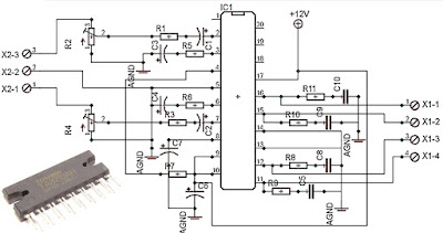
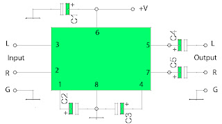
7200W Car Power Amplifier AUDIOBOSE, this car power amplifier 7200W on a power amplifier boxes. But actually this car power amplifier can't give output power 7200W. Car power amplifier with series AB700.4 , have 4 channel speaker output. It can bridge on rear speaker for using car subwoofer speaker , this inside power amplifier.  AUDIOBOSE Car Power Amplifier Top View.  Car power amplifier input output and setting.  Car power amplifier PCB and Component's Final Transistor Car Power Amplifier using TIP41 and TIP42

1200Watt Car Power Amplifier Audiobose

Image
1200Watt Car Power Amplifier Audiobose V12 USC-7720 , 4 channel output speaker 4 x 300 Watt / Bridge 1 x 600W and 2x300W. Bridgeable Power amplifier can using to drive Subwoofer Speaker. you can using Subwoofer Speaker 350W 8 Ohm for matched with this car amplifier . Preamp using IC4558. This car power amplifier inside :

MOSFET based amplifiers

Image
MOSFET based amplifiers as we all know are outstanding with their sound qualities and they can easilly beat the performance of other counterparts based on power transistors or linear ICs. However amplifiers based on mosfets are not always easy to design or make. Moreover after assembling a prototype, testing to perfection always remains an issue with new electronic hobbyists. You might have come across many hi-fi complex mosfet amplifier designs, but might have not dared making it just because of the above reasons. The simple mosfet amplifier circuit diagram is super simple to build and yet will provide you with a crystal clear 100 watts of raw music power that all the listeners will cherish for a long time. The idea was developed a long time ago by the Hitachi researchers and still it remains one of the favorite designs of all time considering the involved simplicity against quality. Looking at the figure we can understand the circuit with the following points: The involved

Stereo Low power audio amplifier circuit

Image
Stereo Low power audio amplifier circuit og Audio amplifier has a power output of 2 x 2.3 Watt, which uses IC KA2206, KA22061, LA4180, LA4182, LA4183, LA4550, LA4555, LA4558. The required voltage for at least 6 volts to 13 volts DC maximum. Component takes is a ic that I mentioned above one of them, and several capacitors elco. This Schematics low power amplifier Component Description Stereo Low power audio amplifier circuit C1 = 1uF C2 = 100uF C3 = 100uF C4 = 100uF C5 = 0.1uF C6 = 470uF C7 = 1uF C8 = 100uF C9 = 100uF C10 = 100uF C11 = 0.1uF C12 = 470uF ICs can use the ic which I mention above for each ic datasheet can be seen itself.

1000W ICs audio amplifier with PA03

Image
This is a circuit of amplifiers are based on the most high-ic power that I have ever known. Because the output is issued up to 1000 watts with the impedance RL 4Ohm. Current supply 120mA, and 30A output current. Minimum input voltage of about 30V and a maximum voltage up to 150V. This is an audio amplifier that I have come across use ICs that maximum voltage up to 150V and output power up to 1000W , the scheme below gan. Part List Resistor R1 = 10K R2 = 10K R3 = 220K R4 = 0.18R 5W R5 = 2.2R 2W R6 = 0.18R 5W Capacitor C1 = 1uF C2 = 1000uF C3 = 68pF C4 = 1000uF Inductor L1 = 4MH IC U1 = PA03

Car power amplifier with TA82010AH

Image
IC TA8210AH is ic often used in amplifiers used in the room, It is suitable for power amplifiers car speakers taht fit and wear ell, surely this amplifier circuit works with a maximum also high quality. Supply voltage is not too high , only 12 VDC and is also good at high current. For high current amplifier power of the stronger . You can use the batteries that have current 10 A or higher . Power output up to 200W stereo with 8 Ohm impedance. Part List : R1 =1K R2 =50K trim R3 =1K R4 =50K trim R5 =680R R6 =680R R7 =150K R8 =2R2 R9 =2R2 R10=2R2 R11=2R2 C1 =1uF C2 =1uF C3 =47uF C4 =47uF C5 =100n/400V C6 =220uF C7 =220uF C8 =100n/400V C9 =100n/400V C10=100n/400V IC1=TA8210AH X2-3=in R X2-2=gnd X2-1=in L X1-1,X1-2=Out R X1-3,X1-4=Out L

STK 4050 - 200Watt Power Amplifier Circuit

Image
Amplifier circuit with IC STK is tough and good quality. In this article an amplifier circuit with IC STK another base. Power "Amplifier 200Watt By STK4050" is an audio amplifier of the STK family with 200Watt power. To create a power amplifier with the STK4050 IC is not require many external components. Power Amplifier uses symmetric 30Volt power supply system. Power Amplifier With this STK4050 can reproduce the power 200 Watts at 8 Ohm load spaker. In making Power Amplifier 200Watt With this STK4050 do not forget to provide adequate heat sink for the IC STK 4050 in order to avoid overheating. Schematics Amplifier STK4050-STK4046 PCB Layout Amplifier Series Power Supply for Power Amplifier 200Watt By STK4050 been displayed in one image with a series of "Power Amplifier" 200Watt With STK4050 above. IC STK 4050 in this series there are several types on the market including STK4050II, STK4050V and STK4050. And below is a list of STK ICs are u

High Power Audio Amplifier 2800W

Image
High Power Audio Amplifier 2800W, Mono power amplifier ouput is 1400Watt / channel. and this circuit is mono power amplifier circuit . See schematic :  Click schematic to view larger See description at source link page Source : High Power Amplifier 2800W

2 x 2,3 Watts power amplifier schematics

Image
This circuit is one of several series of power amplifiers that have output / low output power. This amplifier output is only possess more or less 4Watt. Or 2 X 2Watt stereo power amplifier. Minimum required voltage is not less than 3 volts and a maximum voltage of no more than 14 volts, and voltage must be rectified and filtered to obtain the maximum of the processed audio. Component List : R1 = 2,7R R2 = 2,7R C1 = 1uF C2 = 1uF C3 = 100uF C4 = 220uF C5 = 100uF C6 = 100uF C7 = 220uF C8 = 0.1uF C9 = 0.1uF C10 = 470uF C11 = 470uF U1 = ULN3750B

2x70Watt Stereo Power Amplifier Circuit

Image
Stereo Power Amplifier is 2x70Watt STA550 chip audio power with BASH concept that can be connected with digital device. 2x70Watt STA550 Stereo Power Amplifier is an amplifier with BTL system with symmetrical power supply with ground. Power amplifier STA550 uses power output transistor which is on the chip and is set to produce a high efficiency audio power. Power output on the STA550 is using the system without copling ac bridge (direct) and zero offset. Strengthening of the STA550 from stereo power amplifier is +12 dB. 2x70Watt STA550 Stereo Power Amplifier is equipped with temperature sensors for protection from overheating and current-limiting protection system for power amplifier. 2x70Watt STA550 Stereo Power Amplifier is equipped with standby and mute controls to regulate silent or active mode power amplifier. Feature Stereo Power Amplifier 2x70Watt STA550 : Monochip Bridge Stereo Amplifier dengan Bash® Architecture 55+55w Output Power @ Rl = 4/8 W, Thd = 0.5% 70+

Low power stereo power amplifier schematic

Image
Low power stereo power amplifier schematic This schematic have require minimum voltage at 1Volt and maximum volotage at 9 Volt. Maximum output power 2 X 0.6W. Part List: Capacitor C1 = 100uF C2 = 220uF C3 = 220uF C4 = 220uF C5 = 220uF IC = ULN3782

20W amplifier circuit schematic with mute switch

Image
This is a series of audio amplifier using ic and equipped with a mute switch. This circuit using ic and has 20W output impedance 4 ohms. Scheme and a list of components can be seen below. Part List : Resistor  R1 =  3.3K R2 = 39R R3 = 39R R4 = 3.3K R5 = 3R R6 = 3R Capacitor C1 = 1uF C2 = 1uF C3 = 10uF C4 = 100uF C5 = 100uF C6 = 220uF C7 = 0.1uF C8 = 0.1uF IC IC = ULN3793W

TBA611 amplifier schematic

Image
This amplifier circuit requires voltage ranging from 4Volt to 12Volt, a relatively low voltage. And strong currents needed to obtain a good sound is not too big. This amplifier circuit has a power output or speakers 1W. The output is very small when compared with the voltage amplifiers high. To use it can be used in radio tuner or radio receiver. The circuit schemes can be seen below. Technical information Vcc                = 4,5-15 V Pout               = 1 W RL                 = 8 Ohm Ft                   = 50-15 Khz Icco               = 10 mA Package         = TABS4-14 Manufactered = RFT

TDA2003 made for Car amplifier circuit

Image
This is a very popular series of amplifiers audio users who require maximum aduio results and of course with a relatively cheap price. This circuit requires a minimum voltage and maximum 9 Volt and 30 Volt. This amplifier circuit using ic TDA2003, which is used in car audio power, because of making these amplifiers can easily be made on each speaker of the amplifier. By using ic and component quality is very good circuit used separately. The circuit can be seen below.   Technical information: Supply voltage = 12V Output             = 10W 

Very Low output power amplifier with 5G37 IC

Image
This circuit requires a voltage of 6-12 Volts. To have a good quality of this series with the voltage necessary suplly good too. The definition of good that is filtered and does not release much ripple voltage and using large-capacity condenser elco issued for the bass is strong enough. See below this circuit : Technical information about power amplifier with IC 5G37 Datasheet IC 5G31A Vcc                = 6-12 V Pout               = 0,4 W RL                 = 8 Ohm Ft                   = 40-17 Khz Icco               = 15 mA Package         = TABS1-14 Manufactered = China

STK013 Amplifier Circuit

Image
On the amplifier circuit using ic STK, the same as my previous posting. However, in the above circuit has 2 inputs and 2 outputs, or commonly called a stereo amplifier. This issue of power amplifier 2 x 18Watt and has impedance 8. To stress that it takes about 35-38Volt. Component list : Resistor R1 =  390K R2 = 390K R3 = 220K R4 = 220K R5 = 220K R6 = 220K R7 = 100R R8 = 1R R9 = 9.1K R10 = 9.1K R11 = 1R Capacitor C1 = 10uF C2 = 10uF C3 = 0.47uF C4 = 0.47uF C5 = 220uF C6 = 0.047uF C7 = 4700uF C8 = 100uF C9 = 1000uF C10 = 100uF C11 = 4700uF C12 = 470uF C13 = 0.047uF IC U1 = STK013 source: www.elcircuit.com

IC LM12 , 150 Watts high power amplifier

Image
To supply the required voltage to the  amplifier circuit minimum of 7 Volt and a maximum of 24 volts . Incurred sizable ouput for amplifier ic 300 W maximum output. Part List : R1_____________________________________10K R2_____________________________________10K R3_____________________________________220K R4_____________________________________2.2R 2W C1_____________________________________1uF C2_____________________________________1000uF C3_____________________________________68pF D1_____________________________________BY229 D2_____________________________________BY229 L1_____________________________________4MH IC1____________________________________LM12

140W Amplifier Circuit ( 2x 70 Watt )

Image
Stereo Power Amplifier is 2x70Watt STA550 chip audio power with BASH concept that can be connected with digital device. 2x70Watt STA550 Stereo Power Amplifier is an amplifier with BTL system with symmetrical power supply with ground. Power amplifier STA550 uses power output transistor which is on the chip and is set to produce a high efficiency audio power. Power output on the STA550 is using the system without copling ac bridge (direct) and zero offset. Strengthening of the STA550 from stereo power amplifier is +12 dB. 2x70Watt STA550 Stereo Power Amplifier is equipped with temperature sensors for protection from overheating and current-limiting protection system for power amplifier. 2x70Watt STA550 Stereo Power Amplifier is equipped with standby and mute controls to regulate silent or active mode power amplifier. Feature Stereo Power Amplifier 2x70Watt STA550 : Monochip Bridge Stereo Amplifier dengan Bash® Architecture 55+55w Output Power @ Rl = 4/8 W, Thd = 0.5% 70+70

MOSFET Audio Amplifier circuit 70 Watt power output

Image
MOSFET Audio Amplifier circuit 70 Watt power output This is use the MOSFET power amplifier circuit, amplifier circuit has a very good sound quality. With the noise is quite small, thus making the amplifier circuit is suitable for you to try. Here's the circuit. Click to view larger.  Power amplifier with a 70Watt power is able to issue a clear voice, and very and good loud.

LED bar-graph meter circuit

Image
Several LED above and other components used to determine the signal amplifier, when in a state of high and low . If the signal received from the amplifier circuit is high then the LED lamp are lit up everything and more bright LED lamps, but otherwise if the received signal is low then the lights on only one or two , even absent or faint. To use the circuit you can connec with the output amplifier or speaker output , if there is reinforcing the other in the amplifier , can be connected to the output.

Audio amplifier circuit with IC STK0039 (good quality amplifier)

Image
Although the output of which was issued in this circuit only 35watts maximum, but th esound can be issued harsh , loud , and clear. If the voltage is fit and clean , how to assembly , components are good , the right speakers , this circuit will definitely make a sound that good to hear the ear. See audio amplifier circuit  below : Technical Information : Vcc Max = 45V Vcc TYP = 30V Po            = 35W RL           = 8Ohm Icco TYP = 40mA Icco Max = 80mA I Max      = 10A The amplifier can use to : tuner , subwoofer surround amplifier , surround amplifier , subwoofer system , car amplifier , PC amplifier , DVD/CD amplifier , Room amplifier . Because this amplifier good quality amplifier circuit.

Power Amplifier Class-A circuit

Image
This is a design schematic Class A power amplifier . This is a close as possible in operating parameter  the  Under Classes is class B , to aid comparison ; in particular the NFB factor remains 30dB at 20 kHz. The front end is similiar to class B amplifier. This circuit uses a standart quasi output. This may be replaced by a CFP stage without problems. In both cases the distortion is extremely low, but gratifyingly the CFP proves even better than quasi , confirming the simulation results for output stages in isolation. About Class-A amplifier , in this class is the highest class from another class. Classes below begin from AB to Class S. In a Class-A amplifi er current fl ows continuously in all the output devices, which enables the nonlinearities of turning them on and off to be avoided. They come in two rather different kinds, although this is rarely explicitly stated, which work in very different ways. The fi rst kind is simply a Class-B stage (i.e. two emitter-followers working b

4X15W car amplifier circuit

Image
This circuit is a little different because it is a four channel amplifier. Each channel of this amplifier can deliver an output of 15Watts into a 4 ohm speaker. The amplifier can be operated from a single 12V DC supply and this makes it possible to use this amplifier in car audio applications too. 4 X 15 Watt Mini Power Amplifier Circuit diagram : 4X15W-amplifier-circuit Diagram 4 X 15 Watt Mini Power Amplifier The circuit is based on the 15W BTL X 2 channel audio power amplifier IC TA8215 from Toshiba. Even though chip is specifically designed for car audio applications it can be also used for home audio applications. Two TA8215 ICs are used here in order to obtain a 4 channel amplifier system. The circuit is designed almost exactly as per the application diagram in the ICs datasheet. Pins 7 and 19 are the Vcc pins of the ICs internal integrated power amplifier stages and these pins are connected to the positive supply. Pin 9 is the Vcc pin for ICs internal preamplifier

LA4440 Power Amplifier Circuit

Image
This is a very simple circuit power amplifier with IC LA4440. This circuit is a circuit the first time i learned to make a power amplifier. Power output 2 X 20 Watt with stereo speakers. Minimum Voltage 9 Volt and maximum voltage 24 V. The Circuit is also very easy to make. For novices , this circuit is suitable for use . The material is also readily available at electronics store.  See schematic below : The Speaker are matched with woofer speaker with impedance 4 Ohms. And voltage can be stabilized with IC 7812 but must be reinforced such us transistor.

Amplifier with IC TDA2004

Image
See this circuit below: Datasheet IC TDA2004 Vcc                = 8-18 V Pout               = 2X 12 W RL                  = 2 Ohm Ft                   = 20hz - 20Khz Icco                = 65 mA Package         = SIP1-11 Manufactered = SGS-ATES Other IC TDA2004 , In this circuit you can use the following IC : A2000V A2005V TDA2005 TDA2005M MPC2005 Or you can call Persamaan IC TDA2004

LM1875 | 20 Watt Audio Power Amplifier

Image
20 Watts Power Amplifier circuit can be made ​​with an IC power amplifier LM1875. IC LM1875 is a single chip power amplifier from National. 20 watts audio amplifier with LM1875 is a low power amplifier with good quality to the room. To assemble the amplifier 20 watts with IC LM1875 component is not needed much support. 20 watts power amplifier using LM1875 IC in this article using symmetrical power supply. The virvuit of 20 watts audio power amplifier with IC LM1875 can be used as an experiment or first project for the reader, because it is simple and assembly of high success. Schematic Amplifier LM1875 LM1875 amplifier circuit with the above may result in the strengthening of the voltage up to 27dB for each channel (1 channel 1 IC). Strengthening the voltage can be changed by changing the feedback that is R5 R (on the circuit above using R 22K). But the tension reinforcement can not be less than 20 dB because it can cause oscillation. For the power supply or power supp

Mosfet Power Amplifier 70W

Image
There are possible alternative input stage transistors, the Toshiba 2SA970BL and 2SC2240BL, which appear to be good substitutes for the Hitachi 2SA1085E and 2SC2547E. The ‘BL’ suffix is the high gain group. Alternatives for the Sanyo 2SC2911 and 2SA1209 are the Toshiba 2SC3423 and 2SA1360. 70W Mosfet power amplifier Circuit Diagram This 70W power amplifier is designed for quality rather than quantity, and if much higher power is really needed there are other more suitable design approaches. This is an awesome amplifier circuit, and this is the older version�(MJR7-Mk3). There is new version released (MJR7-Mk5) for better quality and performance, just go to THIS PAGE for complete circuit explanation. source

5.1 surround amplifier circuit schematic

Image
This 5.1 surround amplifier circuit schematic use the IC AN7168 as the main component from this circuit . Minimum voltage required 12V and maximum voltage 24V , I recomended it 12 V because the voltage support on are components. But if you want to better a loud sound you can raise it.  Maximum power output 40W with impedance 4 ohm . This 5.1 surround amplifier circuit schematic also support to make surround sound or 5.1 speaker. Use this amplifier on rear speaker , left right , and center but dont use to subwoofer speaker. See 5.1 surround amplifier circuit schematic below : Click to view large If you want to make a 5.1 surround sound you must make 5 the circuit of 5.1 surround amplifier circuit schematic , for left and right speaker , rear left and right speaker , and center speaker. Use the subwoofer speaker with support amlplifier subwoofer circuit .

TDA2822 made for 5.1 audio amplifier system

Image
Circuit combination of the 3 IC TDA2822  above can be used for 5.1 audio power amplifier system with low power output . The input signal used is analog signal not digital (SPDIF) , so it needed some input to the jack input. The speakers are suitable for use have impedance 8 Ohms , and with power 4 Watt, to Left , Right , Rear pair , center , and subwoofer speakers. To run this circuit , is also required circuit for volume control as tone control . Component and technical Information : C1-C6 : 220uF/25V C7-C9 : 47uF/16 V IC       : TDA2822 x3 CON-1: VCC +12volts DC CON-2: Ground CON-3: Left Speaker CON-4: Right Speaker CON-5: Rear Speaker CON-6: Rear Speaker CON-7: Center Speaker CON-8: Subwoofer Speaker X1-1:Ground X1-2:Subwoofer Input X1-3:Center Input X1-4:Rear Input X1-5:Rear Input X1-6:Right Input X1-7:Left Input See this Printed circuit board below: circuit and PCB Design use Cadsoft Eagle Software

Power amplifier circuit with IC LM386

Image
IC LM386 is working for the amplifier audio circuit with a low power output , range from 0.325 watts to 2 watts with impedance 8 ohm. In this circuit requires voltage of 12 volts to the maximum work, and maximum current 3 Amp. Components List : R1=33K / 0,25W R2=1K / 0,25W R3=10R / 1W C1=100n C2=0,1uF/35V C3=100uF/16V C4=220uF/35V C5=4,7uF/16V IC1=LM386 Connector Instruction: X-1  = Input , connect to output X-2  = Input Ground X1-1= V+ , 12 Volt DC X1-2= V-/ Ground X1-3= Speaker+ X1-4= Speaker-

OCL 150 Watt with 2N3055 and MJ2955

Image
This is OCL 150 W mono audio amplifier circuit , with impedance 8 Ohms. The supply voltage using 25 volt DC with triple voltage + ,- ,ground. see below this circuit : Buffer amplifier use PNP transistor is A564 / A733 /A1013 and NPN use D400 / D438. Driver Amplifier use NPN transistor is TIP31 / TIP41 / D401, and PNP transistor use TIP32 / TIP42 / B546. For the transistor booster or end , here I use a 2 x 20355 and MJ2955 . This anplifier is recomended to full range speakers. See pcb line and construction audio amplifier below : Click to view larger PCB line Components are already installed The booster amplifier already installed.