Posts

Showing posts with the label Intregated Circuit Amplifier

STK013 Amplifier Circuit

Image
On the amplifier circuit using ic STK, the same as my previous posting. However, in the above circuit has 2 inputs and 2 outputs, or commonly called a stereo amplifier. This issue of power amplifier 2 x 18Watt and has impedance 8. To stress that it takes about 35-38Volt. Component list : Resistor R1 =  390K R2 = 390K R3 = 220K R4 = 220K R5 = 220K R6 = 220K R7 = 100R R8 = 1R R9 = 9.1K R10 = 9.1K R11 = 1R Capacitor C1 = 10uF C2 = 10uF C3 = 0.47uF C4 = 0.47uF C5 = 220uF C6 = 0.047uF C7 = 4700uF C8 = 100uF C9 = 1000uF C10 = 100uF C11 = 4700uF C12 = 470uF C13 = 0.047uF IC U1 = STK013 source: www.elcircuit.com

IC LM12 , 150 Watts high power amplifier

Image
To supply the required voltage to the  amplifier circuit minimum of 7 Volt and a maximum of 24 volts . Incurred sizable ouput for amplifier ic 300 W maximum output. Part List : R1_____________________________________10K R2_____________________________________10K R3_____________________________________220K R4_____________________________________2.2R 2W C1_____________________________________1uF C2_____________________________________1000uF C3_____________________________________68pF D1_____________________________________BY229 D2_____________________________________BY229 L1_____________________________________4MH IC1____________________________________LM12

140W Amplifier Circuit ( 2x 70 Watt )

Image
Stereo Power Amplifier is 2x70Watt STA550 chip audio power with BASH concept that can be connected with digital device. 2x70Watt STA550 Stereo Power Amplifier is an amplifier with BTL system with symmetrical power supply with ground. Power amplifier STA550 uses power output transistor which is on the chip and is set to produce a high efficiency audio power. Power output on the STA550 is using the system without copling ac bridge (direct) and zero offset. Strengthening of the STA550 from stereo power amplifier is +12 dB. 2x70Watt STA550 Stereo Power Amplifier is equipped with temperature sensors for protection from overheating and current-limiting protection system for power amplifier. 2x70Watt STA550 Stereo Power Amplifier is equipped with standby and mute controls to regulate silent or active mode power amplifier. Feature Stereo Power Amplifier 2x70Watt STA550 : Monochip Bridge Stereo Amplifier dengan Bash® Architecture 55+55w Output Power @ Rl = 4/8 W, Thd = 0.5% 70+70...

Audio amplifier circuit with IC STK0039 (good quality amplifier)

Image
Although the output of which was issued in this circuit only 35watts maximum, but th esound can be issued harsh , loud , and clear. If the voltage is fit and clean , how to assembly , components are good , the right speakers , this circuit will definitely make a sound that good to hear the ear. See audio amplifier circuit  below : Technical Information : Vcc Max = 45V Vcc TYP = 30V Po            = 35W RL           = 8Ohm Icco TYP = 40mA Icco Max = 80mA I Max      = 10A The amplifier can use to : tuner , subwoofer surround amplifier , surround amplifier , subwoofer system , car amplifier , PC amplifier , DVD/CD amplifier , Room amplifier . Because this amplifier good quality amplifier circuit.

LA4440 Power Amplifier Circuit

Image
This is a very simple circuit power amplifier with IC LA4440. This circuit is a circuit the first time i learned to make a power amplifier. Power output 2 X 20 Watt with stereo speakers. Minimum Voltage 9 Volt and maximum voltage 24 V. The Circuit is also very easy to make. For novices , this circuit is suitable for use . The material is also readily available at electronics store.  See schematic below : The Speaker are matched with woofer speaker with impedance 4 Ohms. And voltage can be stabilized with IC 7812 but must be reinforced such us transistor.

Amplifier with IC TDA2004

Image
See this circuit below: Datasheet IC TDA2004 Vcc                = 8-18 V Pout               = 2X 12 W RL                  = 2 Ohm Ft                   = 20hz - 20Khz Icco                = 65 mA Package         = SIP1-11 Manufactered = SGS-ATES Other IC TDA2004 , In this circuit you can use the following IC : A2000V A2005V TDA2005 TDA2005M MPC2005 Or you can call Persamaan IC TDA2004

5.1 surround amplifier circuit schematic

Image
This 5.1 surround amplifier circuit schematic use the IC AN7168 as the main component from this circuit . Minimum voltage required 12V and maximum voltage 24V , I recomended it 12 V because the voltage support on are components. But if you want to better a loud sound you can raise it.  Maximum power output 40W with impedance 4 ohm . This 5.1 surround amplifier circuit schematic also support to make surround sound or 5.1 speaker. Use this amplifier on rear speaker , left right , and center but dont use to subwoofer speaker. See 5.1 surround amplifier circuit schematic below : Click to view large If you want to make a 5.1 surround sound you must make 5 the circuit of 5.1 surround amplifier circuit schematic , for left and right speaker , rear left and right speaker , and center speaker. Use the subwoofer speaker with support amlplifier subwoofer circuit .

Power amplifier circuit with IC LM386

Image
IC LM386 is working for the amplifier audio circuit with a low power output , range from 0.325 watts to 2 watts with impedance 8 ohm. In this circuit requires voltage of 12 volts to the maximum work, and maximum current 3 Amp. Components List : R1=33K / 0,25W R2=1K / 0,25W R3=10R / 1W C1=100n C2=0,1uF/35V C3=100uF/16V C4=220uF/35V C5=4,7uF/16V IC1=LM386 Connector Instruction: X-1  = Input , connect to output X-2  = Input Ground X1-1= V+ , 12 Volt DC X1-2= V-/ Ground X1-3= Speaker+ X1-4= Speaker-

Power audio amplifier circuit using IC TA7066P

Image
IC TA7066P is original monolithic Intregated Circuit Audio Power Amplifier. Package IC is SIP10-16 and manufactered by TOSHIBA.  The above sequence is a series of low-grade intregated circuit amplifier , which was very small output . But this amplifier is very high impedance power output. For more details , see description below. Technical information : Min. Voltage   : 8   Volts DC Max. Voltage  : 25 Volts DC Max. Power    : 0,3 Watts Impedance      : 150 Ohms Min. Currents : 2,8 mA

30 Watt subwoofer power amplifier circuit

Image
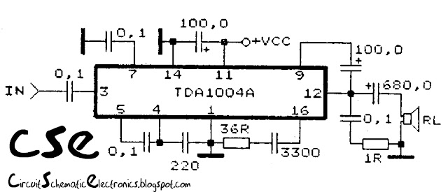
This circuit use IC TDA1004A to main operation .IC is very nice and durable if used properly and correctly, by the way supply the correct voltage , don't supply more voltage than 20 volts, because it can damage the IC. This circuit suitable for subwoofer speakers, but this amplifier  is mono.See schematic and troubleshooting below : If the circuit above not working , posible cause is on : Supply voltage. IC Damaged or installation inverted. Component damaged . Installation components inverted. Line break PCB. Input not connected or input connect to ground. Output speaker not connected.

Audio Power Amplifier based on IC AN7108

Image
This is power amplifier circuit using IC AN7108 as based for amplifier. See this circuit diagram below: Datasheet IC AN7108 Vcc                = 1-6,6 V Pout               = 2X 30 mW RL                 = 32 Ohm Ft                   = 20-20 Khz Icco               = 14 mA Package         = DIP-16 Manufactered = MATSUSHITA

Audio Amplifer using IC TBA 611

Image
This Circuit Audio Amplifer with IC TBA 611 require voltage  4,5 to 15 Volt. I recomended to this circuit supply with 12 volt . Output audio is mono with power 1 Watt. See this circuit and datasheet IC TBA611 below: Datasheet IC TBA 611 Vcc                = 4,5-15 V Pout               = 1 W RL                 = 8 Ohm Ft                   = 50-15 Khz Icco               = 10 mA Package         = TABS4-14 Manufactered = RFT

TBA810 Power Amplifier

Image
Circuit Audio Amplifer with IC TBA810 See this Circuit Below: Datasheet IC TBA 810 Vcc                = 4-20 V Pout               = 7 W RL                 = 4 Ohm Ft                   = 30-18 Khz Icco               = 13 mA Package         = TABS3-12 Manufactered = ITT other IC TBA 810 , In this circuit you can use the following  IC  :  A205K A208E A208K A210E A210K DG810 K174YH7 K17YH9 MA873 TBA310AS TBA790D TBA790U TBA790S TBA810AS TBA810AT TBA810DS TBA810DAS TBA810S TBA810T TCA15OD TCA15OU TCA15OS TCA15OT TCA830 TCA830A TCA830S TCA940 TCA940E UL1440 UL1481P Equivalent IC TBA810

Audio Amplifer with IC TDA 1521

Image
See below this circuit: Datasheet IC TDA 1521 : Vcc                = 6-30 V Pout               = 2X 6W RL                 = 8 Ohm Ft                   = 20-20 Khz Icco               = 40 mA Package         = SIP 1-9 Manufactered = Siemens

Very Low Power Output Amplifier

Image
Technical information Datasheet IC 5G37 Vcc                = 6-12 V Pout               = 0,4 W RL                 = 8 Ohm Ft                   = 40-17 Khz Icco               = 15 mA Package         = TABS1-14 Manufactered = China

LM317 Simple Audio Amplifier

Image
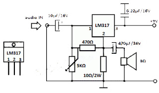
You most likely know that LM317 IC is applied as an practical provide regulator, but did you know it can be applied as an audio amplifier? This is a Low power Amplifier LM317 Simple Audio Amplifier Circuit a audio  designed with LM317 that offers a optimum probable 1W audio strength.  LM317 Simple Audio Amplifier Circuit Diagrams : LM317 Simple Audio Amplifier Circuits Utilization a amazing heatsink for the LM317 IC and modify the 5K various resistor so that you have 4.5V on 10Ω resistor (or LM317 pin 2, Vout).

Power Amplifier for Laptop

Image
Frequently, the sound yield from a laptop's fabricated-in speakers is flat. A capacity intensifier is needed to get an elevated volume. Here is an effortless circuit to intensify the laptop's sound yield.  The circuit is constructed around capacity enhancer IC LA 4440 (IC1) and a few alternate parts. LA4440 is a double channel sound capacity speaker. It has level twisting over a vast run of flat to towering frequencies with exceptional channel detachment. Inbuilt double channels prepare it for stereo and extension speaker provisions. In double mode LA4440 gives 6 watts for every divert and in scaffold mode 19-watt yield. It has swell denial of 46 dB. The sound impact might be grasped by utilizing several 6-watt speakers. Associate binds 2, 6 and ground of IC1 to the stereo jack which is to be utilized with the laptop. Collect the circuit on a customary-reason PCB and encase in a suitable bureau. The circuit works off managed 12V capacity supply. It is suggested to ut...

STK4050 - STK4046 Power Amplifier

Image
Amplifier circuit with IC STK is tough and good quality. In this article an amplifier circuit with IC STK another base. Power "Amplifier 200Watt By STK4050" is an audio amplifier of the STK family with 200Watt power. To create a power amplifier with the STK4050 IC is not require many external components. Power Amplifier uses symmetric 30Volt power supply system. Power Amplifier With this STK4050 can reproduce the power 200 Watts at 8 Ohm load spaker. In making Power Amplifier 200Watt With this STK4050 do not forget to provide adequate heat sink for the IC STK 4050 in order to avoid overheating. Schematics Amplifier STK4050-STK4046 PCB Layout Amplifier Series Power Supply for Power Amplifier 200Watt By STK4050 been displayed in one image with a series of "Power Amplifier" 200Watt With STK4050 above. IC STK 4050 in this series there are several types on the market including STK4050II, STK4050V and STK4050. And below is a list of STK ICs are u...

3W Stereo Amplifier schematic

Image
3 Watt stereo amplifier circuit using MAX 7910 IC. The MAX9710 a stereo audio power amplifier IC capable of delivering 3Watts of out put to 4 Ohm loads. MAX9710 can be operated from a single 4.5V to 5.5V power supply , makes it ideal for hand held applications.The IC for  3 Watt stereo amplifier circuit  also features thermal overload protection. Circuit Schematics 3 Watt  Stereo Amplifier MAX 7910  3 Watt stereo amplifier circuit   This  3 Watt stereo amplifier circuit   is suitable for small power audio devices such as radio sets and portable CD players. 5 V DC power supply is used for powering the  3 Watt stereo amplifier circuit . 6V battery with an IN 4007 diode series to the positive terminal of it can also be used instead of 5 V DC supply. The  3 Watt stereo amplifier circuit  will get a supply voltage approximately 5 V after 0.7 V voltage drop across diode.

200W Stereo High Power Amplifier LM3886

Image
This audio amplifier designed uses two LM3886 per channel, in parallel circuit, based on the PA100 parallel amplifier detailed in National Semiconductor's application note - AN1192. This amplifier can deliver about 50W into a 8-ohm speaker and 100W into a 4-ohm speaker. This is a stereo amplifier and therefore 4 LM3886s are used. The LM3886 circuit is in a non-inverted configuration, so the input impedance is determined by the input resistor R1, i.e. 47k. The 680 ohm and 470pF resistor capacitor filter network is used to filter out the high frequency noise at the RCA input. The 220pF C4 and C8 capacitors are used to shot out the high frequency noise at the LM3886 input pins. I used high quality audio grade capacitors at several locations: 1uF Auricap at the input for DC blocking, 100uF Blackgate for C2 and C6, and 1000uF Blackgate at the supply filter. LM3886 Power Amplifier Schematics The PCB is designed in a way that the power ground is separated from the signal g...