Posts

Showing posts with the label Transistor Amplifier

Power Amplifier Class-A circuit

Image
This is a design schematic Class A power amplifier . This is a close as possible in operating parameter  the  Under Classes is class B , to aid comparison ; in particular the NFB factor remains 30dB at 20 kHz. The front end is similiar to class B amplifier. This circuit uses a standart quasi output. This may be replaced by a CFP stage without problems. In both cases the distortion is extremely low, but gratifyingly the CFP proves even better than quasi , confirming the simulation results for output stages in isolation. About Class-A amplifier , in this class is the highest class from another class. Classes below begin from AB to Class S. In a Class-A amplifi er current fl ows continuously in all the output devices, which enables the nonlinearities of turning them on and off to be avoided. They come in two rather different kinds, although this is rarely explicitly stated, which work in very different ways. The fi rst kind is simply a Class-B stage (i.e. two emitter-followers ...

OCL 150 Watt with 2N3055 and MJ2955

Image
This is OCL 150 W mono audio amplifier circuit , with impedance 8 Ohms. The supply voltage using 25 volt DC with triple voltage + ,- ,ground. see below this circuit : Buffer amplifier use PNP transistor is A564 / A733 /A1013 and NPN use D400 / D438. Driver Amplifier use NPN transistor is TIP31 / TIP41 / D401, and PNP transistor use TIP32 / TIP42 / B546. For the transistor booster or end , here I use a 2 x 20355 and MJ2955 . This anplifier is recomended to full range speakers. See pcb line and construction audio amplifier below : Click to view larger PCB line Components are already installed The booster amplifier already installed.

Classification Transistor Amplifier

Image
A transistor amplifier must have a DC biasing circuit for several reasons. Especially, we will need two separate voltage supply to provide the desired class bias voltage to the emitter-collector and emitter-base. In fact it is actually only done in certain applications, but found that biasing voltage can be obtained separately from a single supply. Second, the transistor is very sensitive to temperature and creates a condition called thermal runaway. Thermal runaway will quickly destroy the bipolar transistor, because the collector current out of control quickly and will improve to the level of damage and the temperature will rise if there is no stabilizing the temperature at the amplifier to eliminate this effect. A common class for refractive surgery is a Class A, AB, B, and C. All of these classes use the same arrangement of the components to her on the operation of the DC bias transistor Q-point or different. Location of the variation bias point Q for different amplifie...

Spirit Amplifier Schematics

Image
Amplifier circuit built-up is pretty nice not always complex. There are a series of amplifiers that I saw a picture of the kit immediately. The circuit is quite simple, there was the most complex in the pre-amp and its protector. Click to view larger | CSE-Circuit Schematic Electronics How a series of ...Op-amp stage 1 is the heart of the circuit, the input stage with enough power to drive the power transistor. Sensor1 ntc & 2 can be attached to the main heatsink, this is optional so it can be eliminated, its functions to lower the bias voltage value if the heatsink overheating. There is no bias trimpot, R6 and R8 instead divide the voltage so we get <= 0.6V at the base driver tr. If the voltage is just a little more driver transistors can be damaged and could trigger the final transistor is damaged in congregation / pairs. These transistors are used frequently broken, but after replaced by Sanken, safe. Thus the risk of the snaps without a limiter amplifier. A pair of Q1 & ...

Simple Voltage Amplifier

Image
Voltage amplifier is used to strengthen the input voltage. Voltage gain is the ratio of output voltage with input voltage. Where can we set the gain. Did this voltage amplifier applications? Alredy understand , Voltage amplifier can be used before the filter and power amplifier between the input signal and speaker. Remember again telecommunication engineering materials where the voltage amplifier is represented as a repeater in the process of data transmission. The first thing to be done before designing the amplifier voltage gain is desired is to determine because the voltage gain is the main purpose of the voltage amplifier. By the way, the voltage amplifier is an amplifier Class A. Then determine the base sequence that is used along with transistors. In the amplifier voltage, output current (collector) is not so necessary so that the collector current labored as small as possible. All to save energy consumed. So there is no special requirement on the transistor voltage amplifier, wh...

Classical audio power amplifier with IT and OT transformer

Image
The circuit is devote to the radio receiver in which sound ( the gear ) is weak. With the help of this tool , which initially sounds as if far to be clearly audible. Power amplifier does not require much  electrical current source , because all components are not up to over 1 Mega . But the result was incredible because it can enhance the power of  catching the wave signal. Troubleshooting : Wether transistors placement is correct ? Placement Elco ? Check are cable . If all components have benn checked , and the damaged has been replaced . Then try , turn the potentiometer slowly and listen to how the sound output by the speaker.

Booster amplifier circuit

Image
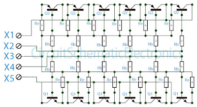
The above circuit is a circuit of booster amplifiers or amplifier end of a power amplifier circuit, Circuit over in the most important influence whether or not , and many more are affected in this final series.  Because the booster circuit is the amplifier end of the work was too heavy components causing the rapid component of the heat. If we are wrong then consequences will install components that can cause fatal damaged direct component , such us the installation of pin emiter, collector , and base everything must be correct. In the circuit above can strengthen booster amplifier with maximum work and everything is evenly split, what is it evenly split ? evenly split the point here is that all components can work with the same voltage and the heat evenly , this is because at each respetive base transistor were given the same constrains and same wattage resistor. And to maintain if the power output is too large then the resistor on Re will hamper so that the transistor is not easil...

600W subwoofer audio amplifier with 20 channel mixer and parametric

Image
This picture below is about my setup subwoofer amplifier with 20 CH mixer and parametric . This amplifier use transformer 10 ampere to supply the power and 3 ampere transformer use to supply mixer and parametric.Elco capacitor that i use for the transformer 10 A, only 10000uF numbered 2. The circuit of amplifiers that i use which is 600 watt mono subwoofer amplifier . And booster amplifier only use 2 Sanken transistors. See picture subwoofer amplifier assemblies below : Looked over the side Front view Back top

1200W power amplifier with sanken

Image
This 1200W power amplifier with sanken using a booster 8 sets sanken , the buffer using transistor D400 and B560 as much 2 sets , and to use part of the driver transistor B546/A940 and D401/C2168 . 1200W power amplifier with sanken have least 20 volts and the voltage to 70 volts maximum with three voltage is +,-,ground. 1200W power amplifier with sanken Power Output 2 X 600 Watt with 8 Ohm Impedance. Circuit audio amplifier 600 Watt Circuit of PCB so from 2  X 600 watts (looked down) Circuit of PCB (looked upon) The above is a circuit of ready to operate , just stay put booster. See also high power amplifier : 2800W High Power Amplifier