Posts

Showing posts with the label Charger Circuit

Circuit Mobile Phone Battery Charger

Image
This post share about Mobile Phone charger circuits, previously you can see other Phone Battery Charger Circuit    or Charger Circuit  . This Charger ciruit use to charging phone battery using IC 7805 for plus voltage regulator or & 7905 for min voltage regulator.  Below is a schematic circuit adapter, power supply , or battery charger (for gadgets, mobile phones , MP4player, smartphone) that is equipped with a 5V voltage stabilizer : Diode Bridge diode bridge, known as a diode bridge is used for the rectifier circuit current ( rectifier ) from AC to DC . to make the diode bridge properly you need to know the type of diode to be used, to suit your needs. example: to make the power supply 12 Volt 3 ​​Ampere diode type 1N5401 is needed, for more detail how to choose the right type of diode to the adapter. Voltage stabilizers are commonly used are the 78XX or 79XX type LM, XX indicates the maximum voltage output is generated. see the example in the circuit sche...

LM350 12 Volt Battery Charger

Image
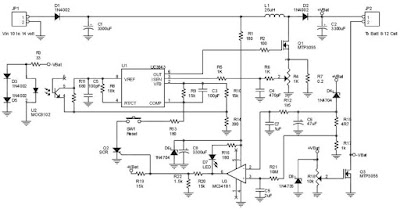
The battery circuit scheme is designed as a source of constant voltage with negative temperature coefficient. Transistor Q1 (BD 140) is used as a temperature sensor. transistor Q2 is used to prevent the battery from discharging through R1 when electrical power is unavailable. Charging circuit is designed based on the LM350 voltage regulator IC. The output voltage of the charger can be adjusted between 13-15 V by varying the POT R6. LM350 will try to keep the voltage drop between the input pin and output pin at a constant value of 1.25V. So there will be a constant current flow through resistor R1. Q1 act here as a temperature sensor with the help of R6/R3/R4 components that are more or less controls the base current of Q1. As connection emitter / base of transistor Q1, the same as other semiconductors, containing the temperature coefficient of-2mV / ° C, the voltage output will also show a negative temperature coefficient. This one is just a factor of 4 large, because the variation of ...

Ultra Fast Battery charger circuit

Image
Ultra Fast Battery Chager for Nickel-Cadmium battery cells [NiCad] which will be discussed in this article is Fast NiCad Battery Charger, called the Ultra Fast Charger Battery Charger NiCad because it can make filling fast NiCad Batteries Cell. A battery charger in Desai has a fast charging capabilities such as Ultra Fast Battery Chager for Nickel-Cadmium battery cells [NiCad] on this article shall be equipped with some ability to protect the battery and charger circuit itself. Feature owned by Ultra Fast Battery Chager for Nickel-Cadmium battery cells [NiCad]  Autoshut-off, is the ability of the charger to stop charging current to a NiCad battery if the capacity NiCad battery is fully charged. Polarity Protection, with the existence of this capability so if there are mounting the battery on the charger upside yan can be known. Constant output voltage Output currents enough to fill some NiCad batteries at once in parallel. Short Circuit Protection, with the existence of this protec...

Powerful Battery Charger Circuit

Image
Series NIMH Battery Charger with IC LT4060 is a NIMH battery charger is powerful, effective and efficient. Featur owned by IC LT4060 is a specialization of a NIMH battery charger. NIMH Battery Charger with IC LT4060 can perform safely charging NIMH batteries because it comes with a battery temperature protection is in charge and the peak level detection system of the battery voltage is in charge.  Battery temperature protection system from the excessive use of NTC temperature sensor. Series NIMH Battery Charger with IC LT4060 also features a charging indicator that will light up when charging and will die when the battery is full. IC 4060 used in this NIMH battery charger from Linear Technology is a production that is designed special for NIMH battery charger. Image Series NIMH Battery Charger with IC LT4060 Description Series NIMH Battery Charger with IC LT4060 R2 potentiometer used for setting the maximum temperature (at set at the value of 4K) LED D1 is a battery charging indica...

Battery Charger based on AVR ATMega 8535

Image
Battery Charger in general can be interpreted as a means to recharge the battery charge. Principles of good charger circuit is capable of providing resources to perform effectively charging the battery, efficient and safe. AVR-Based Battery Charger ATMega 8535 With LCD Display This is an idea that had just emerged from the author. In AVR-Based Battery Charger design ATMega 8535 With LCD Display is using AVR microcontroller processor charger with ATMega 8535, process the data viewer charger with LCD, a safety from a hot temperature with the temperature sensor LM35 and several buttons for setting the charger. And component power charger Battery Charger Based on AVR ATMega 8535 With LCD Display is a FET. Click to view larger Function-Based Battery Charger Part Series AVR ATMega 8535 With LCD Display ATMega 8535 AVR microcontroller serves as the controlling process of the charger. Button S1 - S5 as input data charger settings (setting the current, maximum temperature, peak voltage batterie...

Adapter, power supply and charger circuit

Image
Basically adapter, power supply and charger circuit has a similar construction which consists of a transformer, rectifier (rectifier) and smoothing the voltage. For there is usually an additional power supply voltage stabilizer of voltage regulator IC LM series 78XX or 79XX . Below is a schematic circuit adapter, power supply, or battery charger (for gadgets, mobile phones, MP4player, smartphone) that is equipped with a 5V voltage stabilizer: Adapter, power supply and charger circuit

Flash Lights with HT2014L

Image
Flash Lights with HT2014L This scheme is almost the same with a flash light with LM3909. In this scheme only requires IC HT2014L as a leader, and a resistor and LED. For voltage here need ration power around 4.5 V. You can apply this series to a wider scale in comparing the use IC LM3909. For the scheme are below:

1.3V DC to 12.2V DC Regulator Power Supply

Image
Power supply circuit to generate output below were variations between 1.3V DC to 12.2V DC with 1A current. In addition, the power supply circuit is also equipped with over-current protection or shield against belebih flow. Power supply circuit is very simple, but the quality is quite good, made her basiskan regulator IC LM723 is a pretty legendary. Description: R2 to set the output voltage. The maximum current is determined by R3, over-current protection circuit inside the LM723 to detect the voltage on R3, if it reaches 0.65 V, the voltage output will be off her. So the current through R3 can not exceed 0.65 / R3 although output short-circuit in his. C3 and C4 are ceramic capacitors, as much as possible directly soldered to the PCB, this is because the LM723 is prone to oscillation that is not cool. LM723 works with 9.5V input voltage to 40 V DC and the LM723 can generate its own current of 150mA when the output voltage is not more than 6-7V under input voltage. Specifications: Output...

Automatic Battery Charger Circuit

Image
Basically the circuit designed above have a very simple way of working, where the circuit is designed so that does not happen short circuit or short circuit between the voltage supply with batteries that will be in-charge.  It is true that if any one wants to try to direct mengghubungkan between supply with batteries then the batteries can be sure will be filled. But the current flowing through a charged battery can not be controlled and if the battery is full, the batteries will be damaged or worn out if it remains on the short circuit condition. Working Principle Battery Charger By the time we put an empty battery charging terminals, transistor Q1 will be activated immediately because the current flows through R1 and would trigger a transistor Q1 base. In this condition the flow that would fill the batteries mostly comes from the collector of Q1 is connected directly to the positive terminal of supply. Then during the charging process increases the battery voltage will increase t...

Thermal Controlled battery charger

Image
One way to charge batteries rapidly without abuse is to measure cell temperature and tapper the charge accordingly. The circuit uses a thermocouple for this function. A second thermocouple nulls out the effects of ambient temperature. The temperature difference between the two thermocouples determines the voltage , which appears at the amplifier's positive input. As battery temperature rises, this small negative voltage ( 1 degree Celcius between the thermocouples equals 40uV ) becomes larger. The amplifier, operating at a gain of 4300, gradually reduces the current through the battery to maintain its inputs at balance. The battery charges at a high rate until heating occurs and the circuit then tapers the charge. The values given in the circuit limit the battery-surface temperature rise over ambient to about 5 Degree Celcius. Part List : Resistor R1_____620K R2_____43K R3_____10R R4_____2K R5_____0.6R 5W Capacitor C1_____1uF C2_____0.1uF Diode D1_____1N4148 D2_____1N4001 Transisto...

Rapid battery charger schematic

Image
The First ac voltage from tranformator will be rectified and filtered to the LM723 voltage regulator and the NPN pass transistors setup for constant current supply. The 470 Ohm resistor is limit trickle current the momentary pushbutton (S2) is depressed, the SCR turn  on , and the current flows through previously determined resistor  network.SCR will be turn off if thermal cutout inside the battery pack opens up.

Accu charger with IC LM723C

Image
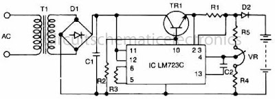
Circuit of 12 V accu / battery charger with IC LM723C. This Accu charger have input from the first transformer - voltage 220 initially V/110V/240V,  the input voltage lowered approximately 12 VAC, then voltage 12 Volts will be rectified by D1 and then filtered by C1 , then filtered and amplified again by IC LM723 and NPN transistor , output voltage is ready to use to charging the accu / battery. Accu charger with IC LM723C Part list : T1 = Transformer , DC 12 V D1 = Diode bridge C1 = 470uF /50V C2 = 1000pF R1 = 4R7 R2 = 5K R3 = 3K9 R4 = 7K5 R5 = 8K2 VR = 2K - 5K trim TR1 = MJ2840 IC = LM723C

USB to phone battery charger circuit

Image
Without any   USB to phone battery charger circuit we can charging phone battery using port on USB computer , but it will quickly damage the phone battery, and the battery will bulge. Because the voltage which was issued on usb is 5 volts , while the average-voltage phone battery 3.5 - 3.7 volts. That's why this USB to phone battery charger circuit is required , this USB to phone battery charger circuit reduce votlage to 3.7 volt usb, but will not reduce currents and  will make a durable phone battery . USB to phone battery charger circuit diagrams List of components : R1 : 1 K R2 : 330 R R3 : 4K7 R4 : 300 R R5 : 27R D1 : 4.7 volt zener /1W C1 : 100uF/16V Q1 : BC548 Q2 : BC558A LED1 : Green Led X1-1   : Vcc USB X1-4   : Ground USB X2-1 , X2-2 : To phone battery See also this printed circuit board ( PCB ) of USB to phone battery charger : USB to phone battery charger printed circuit board

Phone Battery Charger circuit

Image
The circuit above is a simple circuit to charge phone battery . Charge battery uses an output transformer secondary voltage fast-flowing with 9 Volt 350 mA. First voltage 220/110/120/240 VAC 50/60 Hz , will be reduced to 9 volts, then rectified by 4 diodes 1N4007 and then flowed to light Led voltage power resistor 1 kOhms inhibited. + directly to the battery volltage and voltage - across 47 Ohm resistor and Led charge indicator which is inhibited resistor 100 Ohm then directly to the phone battery.

Low battery detector circuit

Image
You feel confused to detect wether a battery is low or high, or you want to be notified if the battery and has expired , this circuit can detect if a battery has begun to decrease its strength. Circuit is based on LM4250 IC is able to detect if the battery runs out and will issue a notification signal.

Battery charger circuit

Image
This cahrger based on chargeing voltage 2,4 Volts per cell , in accordance with most manufacterers recomendation. This circuit pulses the battery under with 14.4 Volts ( 6 cells x 2,4 volts per cell) at a rate 120 Hz.

Variable charger circuit

Image
Indeed the accu charger circuit , the voltage required must be in accordance with voltage batteries , such accu 12 volts the the output voltage should not be above 12 volts and 12 volts should not be too down. If it does not comply with the required voltage , it will make the batteries or accu quickly broken. But not to worry to find the right voltage to charge to accu, the voltage control circuit is equipped to facilitate in determining the voltage. Transformer Primary : 33 turns #22 Secondary : 45 turns #22 Core : Ferroxcube 203 F 181.3C3

Circuit Battery - Charging Regulator

Image
The Charger Circuits / Circuit Battery - Charging Regulator is capable of charging a 12-Volts battery at up to six ampere rate. Other voltages and currents , from 6 to 600 Volts and up to 300 Ampere , can be accomodated by suitable component selection. When the battery voltage reches its fully charged level , the charging SCR shuts off , and a trickle charge , as determined by the value of R4 , continues to flow. See Circuit Battery - Charging Regulator below : Circuit Battery - Charging Regulator You can use the circuit to charge : Cells battery  Accu wet and dry Rechargeable battery

Charger circuit equipped with a regulator circuit output voltage

Image
The circuit charger is equipped with voltage output settings , so that we can regulate how much voltage to charge the battery. And the settings using the potentio making it easier for us managing voltage up to a mV. See charger circuit below : Adjust the circuit by setting the 500 Ohm resistor while it is attached to a fully charged battery. You can use the circuit to charge : Cells battery Wet Accu Dry Accu Nicad battery Solar battery

Accu charger use a diac and triac

Image
This circuit can be used to charge Accu and cells battery , the circuit can has a very stable output that would make the battery last longer  and maximize the added battery capacity. When charge was also quite fast , so it can optimize the time. A diac is used in the gate circuit to provide a threshold level for firing the triac . C3 and R4 provide a transient suppression network. R1 , R2 , R3 , C1 , and C2 provide a hase - shift network for the signal being applied to the gate. R1 is selected to limit the maximum charging current at full rotation of R2.