Posts

Showing posts with the label LED

LED Power Meter

Image
LED power Meter circuit is a simple RF detector using diodes to charge a capacitor. The voltage developed across the capacitor is indicated by a multimeter set to a low voltage range. The circuit is soldered together without the need for a PC board , as can be seen in the diagram below and paper clips are used for the positive and negative terminals of the multimeter. The level power output of an FM transmitter is indicated by the illumination of a LED and the voltage reading on the multimeter gives a further indication of the output. A digital multimeter may be used but the presence of RF may produce a false reading. Likewise, the radiated energy may upset some analogue meters and you may get full scale deflection on the 15v range as well as the 250v range! But the LED won't lie. It will accurately indicate the RF and you can see the change in brightness as you adjust the coils in the output stage. Some of the cheapest and simplest multimeters will give the best results a...
Triac Light Switch as a dimers

Image
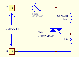
The series of light switches this time slightly different from the voltage of work. The series of light switches can work directly on the AC power network. Light switches are using the main component of TRIAC and LDR. The circuit is very simple and the components were sold in the market. If you want a light reception sensitivity of this circuit can be arranged then the 3.3 MOhm resistor can be replaced with a variable resistor. For more details can be seen from the following series of images. Circuit Diagram With Triac Light Switch series is as dimers, but dimers control performed by the reception of light around the LDR. The lower the intensity cayaha received LDR then  bright lights. For installation LDR need to be considered so as not exposed to light from the lamp directly.

LED Flasher Circuit Using 555 Timer IC

Image
This is a simple LED flasher project that uses a common 555 timer IC for its operation. It is configured as an astable mode which means that its output is a square wave oscillator. Two LEDs are connected to its output in such a way that when one LED is ON, the other LED will turn OFF.  It uses only 10 simple parts that are easily available at any electronic shops. Capacitor C2 charges exponentially through resistors R1, R2 and the resistance of the trimpot. When C2 has charged to about 2/3 VCC it stops charging and it discharges to about 1/3 VCC through R2 and the trimpot resistance via pin 7. This is the standard operation of a 555 timer. When a Vcc of 5 V to 15 V DC is applied to the circuit, the LED will start to flash. The frequency of the flashing can be changed by varying the resistance of the potentiometer or trimpot.Parts List The parts list of the simple LED project is as shown below.

Flip Flop Led Circuit

Image
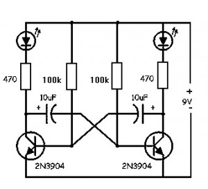
Flip Flop LED Flip flop circuit is a series of free runing multivibrator given the burden of LEDs on each side of the transition changes its output signal. Flip flop circuit with LEDs is quite simple, that is prepared with 2 units and 2 units of 2N3904 transistor circuit tank circuit composed by the RC circuit.  LED indicators signal a change that is placed on each side of the flip flop will be lit in turn by the fire and extinguished the same as the charge and discharge capacitor. Flip flop circuit is quite simple as shown in the picture below. Flip Flop LED series The working principle is the flip flop over when the series voltage source is given then the 10uF capacitor will be charged through R 470 and the LED will then be forwarded to triger the transistor base so that the transistor will turn ON and LEDs. this occurs alternately on each side, so that the LED light will illuminate in turn as well.

Running LED with 4017

Image
Running LED with 4017 complete with PCB layout. The series of 8 LED current is the basis for creating an 8-point LED. Slightly different from the running LED with IC 4017 (decade counter), 8 running this led is lit in sequence, but that has been previously flame does not die when the led is lit afterwards. 8 led to death after led to the fire-8. Meanwhile in the running LED (decade counter), the system LED lights like "point", there is only one LED that flashes between the tenth led. The main component is the IC 74LS164 (SHIFT REGISTER), with its timer is astable multivibrator circuit (using IC NE555). The series will be more efficient when using a stable power supply (regulator) using IC Regulator 7805. Under this scheme a series of stable power supply 5 volts dc.

Make a series letters from the LED

Image
Make a series letters from the LED , Things to consider before making the sign of the LED array, 1) Use LED nodes. 2) Paint the top of the PCB with a dark color (black). 3) Note the LED specifications. In this experiment use a 5mm diameter LED nodes that emit red, specification voltage of 3 volts. The assembly of LED: 1) One letter composed at most 5 columns and 7 rows. 2) One column mostly composed by 6 LEDs are arranged series. 3) Then the fifth column are connected in parallel. 4) Each column given the constraints, Rx, which amount depends on the number of LEDs in one column and depends also on the type of LED (in this experiment that used LED 5mm in diameter, clear with red light beam). 5) In a column consisting of 6 LEDs, Rx = 330 ohm, 5 LEDs, Rx = 560 Ohms, 4 LEDs, Rx = 680 Ohms Remember, this provision applies to 5 mm LED red light beam nodes. 6) Every letter was given FCS9013 transistor amplifier. Here is one letter LED scheme. Medium picture below is the lay out of the 2-lette...

Flash Lights with HT2014L

Image
Flash Lights with HT2014L This scheme is almost the same with a flash light with LM3909. In this scheme only requires IC HT2014L as a leader, and a resistor and LED. For voltage here need ration power around 4.5 V. You can apply this series to a wider scale in comparing the use IC LM3909. For the scheme are below:

230Volt LED Circuit

Image
This is a circuit that is used to menhidupkan LED with voltage 230Volt, 230Volt it so that the voltage must be lowered in accordance with the needs of the LED itself. To lower it even necessary circuit as below.