Posts

Showing posts with the label Inverter

12VDC to 220V AC 500W Inverter Circuit
Image
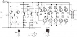
Circuit Inverter 500 Watt 12VDC to 220VAC is made using a transistor. The basiccally of the circuit Inverter 12VDC to 220VAC 500 Watt This is a configuration of 2 pieces of transistors Q1 and Q2 which form a series of Flip-Flop. The output of the flip-flop Q1 and Q2 in the circuit Inverter 12VDC to 220VAC 500 Watt is then broken down for each pulse to complement each other using a series compiled by Q3 and Q4. Output which complement each other is then given to the driver transistors Q5 and Q6 form the transistor 2SC1061. Series Inverter Power Inverter from 12VDC to 220VAC 500 Watt This is a series of parallel transistors Q7 and Q8 are prepared and Q7x and Q8x the form of power with a type 2N3055 transistor 10 pieces. drawing a complete range of circuit Inverter 12VDC to 220VAC 500 Watts can be seen as follows. Step up part of the Circuit Inverter 12VDC to 220VAC 500 Watt 12V CT uses 12V transformer in the secondary and primary 0 - 220V. Working frequency of the Circuit Inverter 12VDC ...

Basically the DAC circuit

Image
Basically the DAC circuit is made to meet the need for the level of influence in the development of digital electronic circuits electronics world. Since the discovery of Silicon and Germanium semiconductor material then quickly there was a revolution in terms of simplicity and accuracy of an electronic circuit. Besides, with the implementation of digital circuits will support at all in terms of data storage and mobility. Lots of data can now be operated with a computer is a data converted from analog signals. For example a voice signal or analog form of video can be played and stored using a computer after analog signals are converted into digital data. Advantages possessed by the digital data than analog signal is a certainty the nature of the data or logic. Digital data only can be divided into two kinds of logic high "1" and logic low "0". Logic 1 represents 5 volts and low logic voltage 0 volts represents. Examples of the advantages of digital signals over anal...

6 to 12 Volt Power Supply Inverter

Image
This inverter circuit can provide up to 800mA of 12V power from a 6V supply. For example, you could run 12V car accessories in a 6V (British?) car. The circuit is simple, about 75% efficient and quite useful. By changing just a few components, you can also modify it for different voltages. Part List: R1, R4 2.2K 1/4W Resistor R2, R3 4.7K 1/4W Resistor R5 1K 1/4W Resistor R6 1.5K 1/4W Resistor R7 33K 1/4W Resistor R8 10K 1/4W Resistor C1,C2 0.1uF Ceramic Disc Capacitor C3 470uF 25V Electrolytic Capcitor D1 1N914 Diode D2 1N4004 Diode D3 12V 400mW Zener Diode Q1, Q2, Q4 BC547 NPN Transistor Q3 BD679 NPN Transistor L1 See Notes MISC Heatsink For Q3, Binding Posts (For Input/Output), Wire, Board source: LINK

Voltage to frequency converter

Image
Changing the voltage to frequency scale in the design of an electronic device is sometimes necessary. The series of articles voltage to frequency converter with the XR 4151 is one answer. Voltage to Frequency converter circuit with the XR 4151 is the idea of time in college, when there are projects to create a tool to hatch chicken eggs. It will be my neighbor also write articles incubators chicken egg-based microcontroller AT89C2051. Maybe there are friends who still remember to this project. Back to the topic of voltage to frequency converter circuit with the XR 4151. IC XR 4151 is a major component of voltage to frequency converter (Voltage to Frequency Converter). From voltage to frequency converter circuit with XR 4151 on the input signal circuit is a DC voltage level. IC XR4151 on voltage to frequency converter circuit serves to convert the voltage level coming into form in the development of the frequency change, where the output frequency range of voltage to frequency converter...

Inverter 5000W with PWM (Pulse Width Modulator)

Image
Inverter 5000W with PWM This inverter uses PWM (Pulse Width Modulator) with type IC SG3524. IC serves as a oscillator 50Hz, as a regulator of the desired output voltage. Input power ranging from 250W up to 5000W output and has. Following a series INVERTER 5000W with PWM (Pulse Width Modulator). Schematic Inverter 5000W with PWM (Pulse Width Modulator) Layout PCB Inverter 5000W with PWM (Pulse Width Modulator) below is the output power settings that can be issued by this inverter: DC voltage and Transformer "T2" winding recommendation: Winding Power Supply 12VDC 750W P: 24V "12-0-12" / S: 220V 1500W 24VDC P: 48V "24-0-24" / S: 220V 2250w 36VDC P: 72V "36-0-36" / S: 220V 3000w 48VDC P: 96V "48-0-48" / S: 220V 3750w 60VDC P: 120V "60-0-60" / S: 220V 4500w 72VDC P: 144V "72-0-72" / S: 220V 5250w 84VDC P: 168V "84-0-84" / S: 220V Transformer used is the transformer CT R1 serves to regulate the voltage to 220v in...

12-Volt to 32-Volt CT converter DC to DC

Image
Kit that can change the normal 12v dc voltage from a car battery, battery bike 12V motor. With the current 7A. so this circuit is very suitable for power car amplifiers and sound systems that use simple 12V battery. Kit converter is also equipped with inputs "SEND" to activate the circuit and also send this interchangeable inputs is connected to the Tape / cd / dvd player of your car. And input "send" is if the non-connected with an output of "send" player car you then connect it to +12 hrs on v from the battery / batteries The series is already in the test kit and has been functioning normally.

High voltage inverter circuit diagram

Image
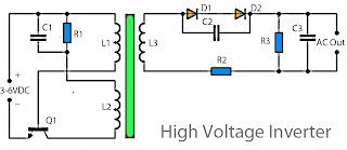
This inverter circuit works with a transistor and transformer and other components to increase the voltage becomes high. Input supply voltage ranging from 3V to 6V DC, later it was raised to high voltage AC. However, in this inverter circuit output current is very small, probably under 0.1A even smaller. However, its use you can apply it on a fluorescent lamp 10W maximum power only, and that too takes time to switch on fluorescent lamps. Part List R1 = 4K7 R2 = 2K2 R3 = 330K C1 = 100nF C2 = 100nF 275V C3 = 0.22uF 275V Q1 = D506 L1 = 100 times winding, with 0.8mm diameter copper wire L2 = 50 times winding, with 0.8mm diameter copper wire L3 = 5000 times winding, with 0.4mm diameter copper wire