Posts

Showing posts with the label Inverter Circuit

3V to 40 Volt DC Converter Circuit

Image
Switching regulator subsystems intended for use asdc to dc converters. 3V to 40 Volt DC Converter circuit | The use of switching regulators is becoming more pronounced over that of linear regulators because the size reductions in new equipment designs require greater conversion efficiency. Another major advantage of the switching regulator is that it has increasednapplication flexibility of output voltage. The output can be less than, greater than, or of opposite polarity to that of the input voltage. The MC34063 series is a monolithic control circuit containing all the active functions required for dc to dcconverters. This device contains an internal temperature compensated reference, comparator, controlled duty cycle oscillator with an active peak current limit circuit, driver, and a high current output switch. This series was specifically designed to be incorporated in step–up, step–down and voltage– inverting converter a...
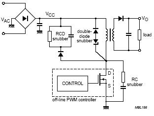
Mosfet Snubber Flyback Converter Circuit

Image
Mosfet Snubber Circuit in Flyback Converter , Typical flyback convertor with drain clamping circuits ZenBlock Zener with integrated blocking diode Philips Semiconductors' new ZenBlockTM replaces double-diode-, RCD - or RC-snubbers in flyback convertors .  Mosfet Snubber Flyback Converter Circuit The new components offer circuit designers the important benefits of lower component count and board usage, reduced EMI, optimal clamping at all loads and higher efficiency . Introducing The new ZenBlock combines the double diode snubber in one package. This leads to the following advantages:  -Fewer components.  -Reduced circuit board space  -Lower EMI by reducing the drain clamp circuit length and area.  -Optimal clamp performance at all loads (compared with RCD and RC snubber)  - Higher efficiency at low loads (compared with RCD and RC snubber) . Previous circuit related to this circuit :  Protection of the Mosfet in flyback power supply

DC- DC Converter 12V to 24V

Image
This simple circuit is a DC-DC converter that converting up 12V source to a 24V . It can be used to run radios, small lights, relays, horns and other 24V accessories from a 12V vehicle with a maximum draw of about 800mA. This DC-DC Converter can be used to charge one 12V battery from another, or step up the voltage just enough to provide necessary overhead for a 12V linear regulator. Using one op-amp as a squarewave oscillator to ring an inductor and another op-amp in a feedback loop, it won't drift around under varying loads, providing a stable 24V source for many applications. With a wide adjustment in output this circuit has many uses.  Parts List R1-R4,R7-R8 100K 1/4W Resistor  R5 470 Ohm 1/2W Resistor  R6 10K Linear Pot  C1 0.01uF Mylar Capacitor  C2 0.1uF Ceramic Disc Capacitor  C3 470uF 63V Electrolytic Capacitor  D1 1N4004 Rectifier Diode  D2 BY229-400 Fast Recovery Diode See Notes Q1 BC337 NPN Power Transistor  U1 LM358 Dual O...

Inverter 5000 Watt PWM

Image
This inverter uses PWM ( Pulse Width Modulator ) with type IC SG3524 . IC serves as a oscillator 50Hz, as a regulator of the desired output voltage. Input power ranging from 250W up to 5000W output and has. Following a series INVERTER 5000W with PWM (Pulse Width Modulator). Schematic Inverter 5000W with PWM (Pulse Width Modulator) Layout PCB Inverter 5000W with PWM (Pulse Width Modulator) below is the output power settings that can be issued by this inverter: DC voltage and Transformer "T2" winding recommendation: Winding Power Supply 12VDC 750W P: 24V "12-0-12" / S: 220V 1500W 24VDC P: 48V "24-0-24" / S: 220V 2250w 36VDC P: 72V "36-0-36" / S: 220V 3000w 48VDC P: 96V "48-0-48" / S: 220V 3750w 60VDC P: 120V "60-0-60" / S: 220V 4500w 72VDC P: 144V "72-0-72" / S: 220V 5250w 84VDC P: 168V "84-0-84" / S: 220V Transformer used is the transformer CT R1 serves to regulate the voltage to 220v inverter R2 serves ...

12V to +/- 20V DC Converter Circuit

Image
100 Watt 12V to +/- 20V DC Converter Circuit DC To DC Converter circuit used to be an convert  voltage DC to DC with different concepts. DC to DC converter circuit +12 V to + /-20V is working to change the battery voltage from 12V DC to 20V DC voltage symmetrical. DC to DC converter circuit is often applied to the power amplifier udio on car audio systems. DC to DC converter circuit uses a TL494 IC as power plsa for the converter.  TL494 IC is a PWM controller with an adjustable frequency from 40-60Hz through a potentiometer. Then from the TL494 PWM signal is given to the driver MOSFET inverter TPS2811P to be given to the power inverter with 2 units of MOSFET transistors. Circuit details can be seen in the figure following the DC to DC converter. DC To DC converter circuit +12 V To + / - 20V  Click to View Larger List Components DC To DC Converter +12 V To + / - 20V R1, R2 = 10  R3, R4, R6, R7 = 1k  R5 = 22k  R8 = 4.7k  R9 = 100k  C1, C2 = 10000uF...

Frequency to Voltage Converter Circuit

Image
IC LM2917 Frequency to Voltage Converter IC LM2917 IC chip is designed specifically as a Frequency to Voltage Converter or Frequency to Voltage converter. In its use to applications Frequency to Voltage Converter IC LM2917 requires few external components.  There are several examples of applications of Frequency to Voltage Converter IC LM2917 datasheet that is included in the LM2917 IC. In this article series Frequency to Voltage Converter IC also taken from the LM2917 datasheet. The advantages of single chip LM2917 Frequency to Voltage Converter is able to provide instantaneous volt output o at time of frequency change 0 Hz. Very easy to apply in measuring the output frequency with the formulation of single-chip Frequency to Voltage Converter VOUT = FIN x VCC x R1 x C1. Then the single-chip LM2917 Frequency to Voltage Converter This configuration requires only the RC only in frequency doubling. And has an internal zener regulator to aimlessly accuracy and stability in frequency-to...

10Mhz to 1 MHz Frequency Converter

Image
10Mhz to 1 MHz Frequency Converter Circuit Part ListIC1 7404 = 1 IC2 7490A = 1 R 1 K = 2 R 3.3 K = 1 C Trim Polymer 39 pF = 1 C Electrophoresis 4.7 uF 16V = 1 C Milar 47 nF 16 V = 1 C Milar 10 nF 16 V = 1 C Ceramic 68 pF 50 V = 1 

6 to 12 Volt Converter

Image
Below its a converter circuit voltage from 6 Volt to 12 Volt DC. 6 Volt to 12 Volt DC Part List : R1, R4 2 .2K 1/4W Resistor R2, R3 4.7K 1/4W Resistor R5 1K 1/4W Resistor R6 1.5K 1/4W Resistor R7 33K 1/4W Resistor R8 10K 1/4W Resistor C1,C2 0.1uF Ceramic Disc Capacitor C3 470uF 25V Electrolytic Capcitor D1 1N914 Diode D2 1N4004 Diode D3 12V 400mW Zener Diode Q1, Q2, Q4 BC547 NPN Transistor Q3 BD679 NPN Transistor L1 See Notes Notes 1. L1 is a custom inductor wound with about 80 turns of 0.5mm magnet wire around a toroidal core with a 40mm outside diameter. 2. Different values of D3 can be used to get different output voltages from about 0.6V to around 30V. Note that at higher voltages the circuit might not perform as well and may not produce as much current. You may also need to use a larger C3 for higher voltages and/or higher currents. 3. You can use a larger value for C3 to provide better filtering. 4. The circuit will require about 2A from the 6V supply to provide the full 800mA at...

Simple Inverter with Two Transistors

Image
The series below is a simple inverter circuit that will change the voltage of 12v dc to 220v ac, with use drive transistor 32 as its tip. Inverter circuit is very simple and easy to assemble and is perfect for just starting to learn to assemble electronic circuits, you can use the transformer 2A to produce about 20 watts output. Do not forget to install coolers in its transistors. good luck.

12V to 220V Inverter Schematics

Image
12V to 220V Inverter Circuit Diagrams, Even though today’s electrical appliances are increasingly often self-powered, especially the portable ones you carry around when camping or holidaying in summer, you do still sometimes need a source of 230 V AC - and while we’re about it, why not at a frequency close to that of the mains? As long as the power required from such a source remains relatively low - here we’ve chosen 30 VA - it’s very easy to build an inverter with simple, cheap components that many electronics hobbyists may even already have 12V to 220V Inverter . 12V to 220V Inverter Circuit Diagrams Though it is possible to build a more powerful circuit, the complexity caused by the very heavy currents to be handled on the low-voltage side leads to circuits that would be out of place in this summer issue. Let’s not forget, for example, that just to get a meager 1 amp at 230 VAC , the battery primary side would have to handle more than 20 ADC !. The circuit diagram...

6V to 220V inverter schematic

Image
Circuit schematic above is one of the voltage inverter circuit , starting from 6-Volt input on the DC current into 220-volt AC output. For maximum output power up to 30W only, and is also very small voltage current. Input voltage plus the entrance on the transistor Q2 to provide the voltage at the collector and then go on Circumference transformer L1 and enter the base. Emitter will be merged ddengan voltage supplied L2 min. And LED 1 is useful as an indicator of whether or not an inverter works especially on the transistor Q2. Part List : R1 = 1K R R2 = 220R C1 = 10nF C2 = 100nF C3 = 47nF C4 = 0,22uF 400V Q1 = 2N5551 Q2 = C5198 LED1 use Green Led Transformer instruction : The above is figure from a place  plastic for copper wire wrapped around, you can also use the marks that have been unused transformer. For the above number are : 1 : Place for copper wire wrapped,with a diameter of 12mm x 10mm. 2 : Hole to place an iron or ferrite rod , with diameter 10mm. 3 : Copper wire that...

3V to High voltage inverter

Image
Inverter circuit on basic of really taking a series of mosquito racket, a racket in which these mosquitoes require only a low voltage. With only 3 Volts course of this series has been able to work. Circuit is raising the voltage by a transformer that can be made yourself with the need of copper wire and ferrite rods. How to making a transformer like that here , but this circuit requires a step-up transformer that are larger and require a lot of coils. This transformer is controlled by a transistor semiconductor 24D506 in this series. To output issued until 1KV or more but issued is very low amperage. This circuit can also be used in fluorescent lamps 10W maximum . When used in fluorescent lamps add another capacitor to the voltage for provoke can turn on the lights. Part List : Resistor R1____1K5 Ω R2____4K3 Ω R3____22M Ω Capacitor C1____100n C2____100n  400V C3____0.2uF 400V Diode D1___1N4007 D2___1N4007 Transistor Q1___ 24D506 Transformer L1___#100 turns L2___#100 turns...

Inverter 12V to 115V with 25 W power output

Image
Low power inverter schematic are only use 9 components , one of which IC 556 , TIP120 NPN Darlington transistor.And turns 10 to 16 Vdc into 60 HZ, output 115 V square-wave power to operate ac equipment up to 25 W. In the circuit first ic originally hires as a timer chip m for stabilizatiom oscilator with components R1 and C1 setting frequency oscilator. Then the two transistor driver, drive the transformer push-pull fashion, When one transistor is biased on , the other circuit cut-off . The transformer is a 120V/18Vct unit that is connected backwards, so that it steps the voltage up rather than down. Oscilator circuit operates from about 4 to 16 V for  stable output.  Part List : R1 = 1K R2 = 12K R3 = 1K R4 = 1/4W C1 = 1uF IC = 556 Q1 = TIP120 Q2 = TIP120 T1 = 120V 18VCT

Simple Inverter circuit with IC556 timer chip

Image
This circuit is low power inverter , in this circuit only save a few components, about 9 parts. Voltage input from 10 volt to 16 volt DC into 60-Hz.  And then voltage will be raised to about 115 V with power 25 W. The first section of IC 556 timer chip is wire as an astable oscilator with R2 and C1 setting the frequncy. The output is available at IC 556 pin 5. The second section is wired as a phase inverter. That output is available at IC 556 pin 9. Schematic low inverter below :   The transformer use 120 V / 18 VCT unit that is connected backwards, so that it steps the voltage up rather than down. At resistor R3 and R4 keep output transistor Q1 and Q2 from loading the transistor. The transistor drive the transformer . The circuit can you use to supply lamp or other electronic devices.

Simple Inverter Circuit from 12 V up to 120V elevated

Image
This is a simple 120 V : 24 V , center - tapped ( CT ) control transformer and four additional components can do the operation. This circuit outputs a clean about 120 volt - 200 volt at 60 Hz and can supply up to 20 Watt . The circuit is self starting and free running. See this simple inverter circuit below : Transistor Q1 and Q2 use 2N5877 or similarity .If Q1 is faster and higher gain than Q2 , it will turn on first when aplly the input power and will hold Q2. Load current and the transformer magnetizing current the flows in the upper half of primary coil, and auto transformer supplies the base drive (two transistor) unti the transformer saturates.The transformator can use the 3A CT transformer an use the secondary coil for input and primary coil use to output, And input use the 12 volt secondary coil. Use 12 battery to power input , such as 12 V accu. You can use the circuit at the time of death PLN electricity , using 12 volt battery or accu , you can turn n a fluorescent...