Posts

Showing posts with the label Power Supply

Power Supply Variable 1.3V - 12.2V 1A Circuit

Image
Power supply circuit to generate output below were variations between 1.3V DC to 12.2V DC with 1A current. In addition, the power supply circuit is also equipped with over-current protection or shield against belebih flow. Power supply circuit is very simple, but the quality is quite good, made her basiskan regulator IC LM723 is a pretty legendary. Description: R2 to set the output voltage. The maximum current is determined by R3, over-current protection circuit inside the LM723 to detect the voltage on R3, if it reaches 0.65 V, the voltage output will be off her. So the current through R3 can not exceed 0.65 / R3 although output short-circuit in his. C3 and C4 are ceramic capacitors, as much as possible directly soldered to the PCB, this is because the LM723 is prone to oscillation that is not cool. LM723 works with 9.5V input voltage to 40 V DC and the LM723 can generate its own current of 150mA when the output voltage is not more than 6-7V under input voltage. Specifications: Output...

6 to 12 Volt Power Supply Inverter

Image
This inverter circuit can provide up to 800mA of 12V power from a 6V supply. For example, you could run 12V car accessories in a 6V (British?) car. The circuit is simple, about 75% efficient and quite useful. By changing just a few components, you can also modify it for different voltages. Part List: R1, R4 2.2K 1/4W Resistor R2, R3 4.7K 1/4W Resistor R5 1K 1/4W Resistor R6 1.5K 1/4W Resistor R7 33K 1/4W Resistor R8 10K 1/4W Resistor C1,C2 0.1uF Ceramic Disc Capacitor C3 470uF 25V Electrolytic Capcitor D1 1N914 Diode D2 1N4004 Diode D3 12V 400mW Zener Diode Q1, Q2, Q4 BC547 NPN Transistor Q3 BD679 NPN Transistor L1 See Notes MISC Heatsink For Q3, Binding Posts (For Input/Output), Wire, Board source: LINK

5 Volt Switching Regulator Power Supply

Image
The switching regulator power supply used LM2575-5.0 on this schematic. You can make the stable voltage by using the 3 terminal regulator like LM317. However, because the output electric current and the inputted electric current are the same approximately, the difference between the input electric power (The input voltage x The input electric current) and the output power (The output voltage x The output current) is consumed as the heat with the regulator. Because it is, the efficiency isn�t good. Data sheet for LM2575 SIMPLE SWITCHER 1A Step-Down Voltage Regulator http://www.national.com/pf/LM/LM2575.htm

Power Supply Variable 1.3V - 12.2V 1A Circuit

Image
Power supply circuit to generate output below were variations between 1.3V DC to 12.2V DC with 1A current. In addition, the power supply circuit is also equipped with over-current protection or shield against belebih flow. Power supply circuit is very simple, but the quality is quite good, made her basiskan regulator IC LM723 is a pretty legendary. Description: R2 to set the output voltage. The maximum current is determined by R3, over-current protection circuit inside the LM723 to detect the voltage on R3, if it reaches 0.65 V, the voltage output will be off her. So the current through R3 can not exceed 0.65 / R3 although output short-circuit in his. C3 and C4 are ceramic capacitors, as much as possible directly soldered to the PCB, this is because the LM723 is prone to oscillation that is not cool. LM723 works with 9.5V input voltage to 40 V DC and the LM723 can generate its own current of 150mA when the output voltage is not more than 6-7V under input voltage. Specifications: Output...
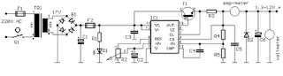
1.3 - 12.2 VDC Variable Power Supply

Image
Power supply circuit to generate output below were variations between 1.3V DC to 12.2V DC with 1A current. In addition, the power supply circuit is also equipped with over-current protection or shield against belebih flow. Power supply circuit is very simple, but the quality is quite good, made ​​her basiccally regulator IC LM723 is a fairly legendary.

Power Supply Variable 1.3V - 12.2V 1A Circuit

Image
Power supply circuit to generate output below were variations between 1.3V DC to 12.2V DC with 1A current. In addition, the power supply circuit is also equipped with over-current protection or shield against belebih flow. Power supply circuit is very simple, but the quality is quite good, made her basiskan regulator IC LM723 is a pretty legendary. Description: R2 to set the output voltage. The maximum current is determined by R3, over-current protection circuit inside the LM723 to detect the voltage on R3, if it reaches 0.65 V, the voltage output will be off her. So the current through R3 can not exceed 0.65 / R3 although output short-circuit in his. C3 and C4 are ceramic capacitors, as much as possible directly soldered to the PCB, this is because the LM723 is prone to oscillation that is not cool. LM723 works with 9.5V input voltage to 40 V DC and the LM723 can generate its own current of 150mA when the output voltage is not more than 6-7V under input voltage. Specifications: Output...

5 Volt Switching Regulator Power Supply

Image
The switching regulator power supply used LM2575-5.0 on this schematic. You can make the stable voltage by using the 3 terminal regulator like LM317. However, because the output electric current and the inputted electric current are the same approximately, the difference between the input electric power (The input voltage x The input electric current) and the output power (The output voltage x The output current) is consumed as the heat with the regulator. Because it is, the efficiency isn�t good. Data sheet for LM2575 SIMPLE SWITCHER 1A Step-Down Voltage Regulator http://www.national.com/pf/LM/LM2575.htm

Power Saver Circuit | Saving electricity

Image
Do you know how to work his usual power saving devices in the market is shaped like a dry battery with a plug into an outlet?. Actually you can create your own tool with much better quality with much cheaper price. Because of the way it works is to reduce the magnitude from cosine curve AC current that will be read on the gauge kilometer. Device work if there is air conditioning load passes through a coil of wire sensors to measure the AC current which is being passed. Power Saver Circuit A very influential component in the AC circuit is a capacitor and inductor. Therefore we need to filter the AC current before it enters our home electricity network. Obviously we did not perform the act of theft of electricity, and this tool will not be detected by the device are as follows . How to installation, Here I would include a scheme of the circuit which will be installed close to the mile. The closer, the more optimal the way it works, use good quality capacitors, for security MCB here, serv...

Power Supply no transformer using IC and MOSFET

Image
Pulsating DC voltage from rectifier D1 - D4 has a peak value 310 V This voltage is supplied to the spout of the power MOSFET T1 through a resistor divider R9. A control circuit ensures MOSFET will only deliver a short dive before and after the voltage through zero meshes. During this time do not go too far pulsating DC voltage 5 V. In a short time the same grading Capacitor C2 will be too fit, long time thereafter he gives the output current. Capacitor result should be worth a very large 10,000 μF. Load current pulses in a short time has a price peak in the 4th order A! Schematics MOSFET use BUZ74 and IC CA3130E Output voltage stability essentially depends on the load. Maximum output current can be 110 mA. Supply for control circuit is obtained from the resistor R2., Capacitor C1 and the diodes D5 and D6. Control circuit is formed penanding window of three op-amp. The correct calibration of the controlling circuit becomes very important. Before the nets are given, first set the P1 in t...

Simple Power supply without transformer

Image
This circuit has a voltage output of about 12 volts with 20mA current voltage. And this series of works using capacitive reactance and resistance are not using, this will reduce the heat on the circuit. To be safe when there is a short-circuit series, always use a fuse on the input voltage is 220V. Here is a series of power supply without a simple transfomer. Power supply Circuit Part List R1 - 1.8K 1W R2 - 100Ω C1 - 0.47µF 400V C2 - 1000µF 50V D1 - 1N4007 D2 - 1N4007 D3 - 1N4007 D4 - 1N4007 ZD1 - 16V Zener Diode ZD2 - 16V Zener Diode ZD3 - 12V Zener Diode

6 - 12 Volt | Adjustable Power Supply Circuit

Image
Power Supply in this article use a regulator that is composed of 2 pieces of NPN transistor. A transistor acts as a power regulator and a transistor again serves as a controller output voltage. Power Supply has an adjustable output with a range of 6-12 VDC. The part that serves as a power regulator is Q1 TIP31. Then the controller output voltage is a voltage divider composed of R3, R4, VR1 and R2 provide bias to the base of Q2 to Q1 mengentrol power regulator. In a series of power supply is mounted 5.1 V zener diode which serves to make the minimum limit the output voltage with Q2. Adjustable Power Supply with transistor circuit Power Supply With transistor circuit is quite simple and can be made with the PCB holes, so for those who want to try to directly mempraktikannya. May the power supply circuit can be useful for readers, especially for friends who need a power supply circuit with the regulator transistor.

Simple Source Voltage Protector

Image
Protection of electronic devices with a DC voltage source of voltage source obligatory reversal, especially protection of the source voltage is reversed. The definition of "Protectors Voltage Sources" in this article are the source voltage surge protector circuit which serves to protect the device from the reversal of the voltage source to the appliance electronics. Source voltage surge protector will expressed in this article are general, so that later in their applications to stay adjusted value of the component with the voltage source needs an electronic appliance. Let us start reviewing Protectors Voltage Source by simple and modest. Source voltage protection with 1 diode Diodes are used as a protector of the source voltage installation tebaliknya voltage source is installed in series with the input line voltage source electronics devices. Installation of surge protector diode as a voltage source is on the positive line voltage source input device. The function is to drai...

Adjustable switching power supply

Image
This circuit supplying current maximum10A with an adjustable output voltage from 0-25 VDC. Adjustable Switching Regulator L4970 Series is built with the main component as a Switching Regulator IC L4970. Switching Regulator L4970 series include not complicated to make his own, which need to be considered is the IC L4970 require sufficient cooling to operate in an optimal and durable. Adjustable Switching Regulator L4970 series are complete can be seen in thethe following figure . Adjustable switching power supply schematics To set the output voltage range Adjustable Switching Regulator L4970 can be in control by adjusting the potentiometer 18KOhm tus.

35 Ampere Power Supply

Image
To make 12Volt 35 Amp Power Supply such as those titles can using LM7812 voltage regulator as the regulator 12 Volt DC and as a power supply can use transistor  TIP2955 . Series Power Supply 12Volt 35 Amp uses 6 units TIP2955 type power regulator transistors. I use a type MJ2955 TIP2955 not because packaging TIP2955 easier to install heatsink. The series 12Volt 35 Amp Power Supply can be loaded up to 35A depending on the travo which we attach. The series 12Volt 35 Amp Power Supply is very simple, because the voltage regulators make use of IC7812 which will leave a power regulator alone. For more details, series 12Volt 35 Amp Power Supply can be seen in thethe following figure . 12Volt 35Ampere schematic If want the maximum currents up to 35A not only reduced the live circuit TIP2955nya power regulator, no need to 6 levels as seen in the image series 35 Ampere Power Supply 12Volt above.

90 Watt Switching Power Supply

Image
Switching Power Supply in this article are able to supply power 90 Watt. Switching Power Supply series is built directly from an AC network system using special IC MC33374 switching power supply in the form of High Voltage Power Switching Regulator and with external components to the other. IC MC33374 IC is a switching power supply designed to operate with an AC voltage source and works as a power switching converter with flyback technique. Switching Power Supply Series has a 15 volt DC output with current up to 6 Ampere. 90 Watt Switching Power Supply Schematic Series 90 Watt Switching Power Supply works by menyearahkan AC source is then used to activate the converter MC33374 system. The output of transformer switching converter MC33374 searahkan again later on as a DC voltage supply to be used for electronic devices.

High Voltage regulator schematics

Image
In this series of essentially the same principle with the power supply, but power supply is working to produce high voltage. And high voltage which is regulated by this series becomes more filtered and either used for electronic devices that are not easily damaged. High Voltage regulator schematics Component List R1_____________1K R2_____________470K R3_____________330K R4_____________20K C1_____________39uF 450V C2_____________39uF 450V C3_____________39uF 450V C4_____________39uF 450V C5_____________10uF 25V C6_____________220nF 250V C7_____________100nF 400V D1_____________1N4007 D2_____________1N4007 D3_____________1N4007 D4_____________1N4007 D5_____________1N4148 D6_____________1N4148 TR1____________MJE13005 TR2____________MPSA92 TR3____________MPSA42

Power Supply with principle of UPS

Image
For UPS Power Supply circuit consists of lowering the voltage, rectifier, charger, batery and regulators. The technique is applied from UPS on the power supply is the use of batery and charger is connected dengang direct coupling with a series diode. For more details can be seen with the following image. Schematics The rectifier in the circuit UPS Power Supply For this to function also as a charger via D1. D3 function is to drain-source voltage of the rectifier to the regulator circuit, when the AC voltage source. D2 serves to drain the batery when the source voltage from AC voltage source does not exist. batery configuration and diode D1, D2 and D3 is adopted from the UPS system. may be useful and can provide inspiration on teman2 all in making backups on the system power supply voltage.

USB powered battery charger circuit

Image
At this time I will share about the series used in the usb to charge battery. Issued voltage 4.7 Volt to 5 Volt DC suitable for battery charge the phone, as well as other batteries.  Below is a circuit where the voltage is removed the usb on the computer will be strengthened by several components so that the voltage used to charge batteries more powerful and filtered, and will make it more durable and long lasting. Part List : R1 = 1 K R2 = 330 R R3 = 4K7 R4 = 300 R R5 = 27R D1 = 4.7 volt zener /1W C1 = 100uF/16V Q1 = BC548 Q2 = BC558A

7812 voltage stabilizer

Image
To obtain a pure DC voltage, then we must consider the regulation voltages and currents that we change from AC to DC current. For that we need some settings that can support our own making and its components were easy to get in the electronics market. This is series Power Supply that can be used on trafo 5 Ampere up to 10 Amperes. If you want to use a larger transformer than 5 Amperes transistor 2N3055 is suggested that the double for the exit of the collector current is larger and in accordance with the current out of the transformer. How pemasanganya enough in the series on all sides of the pin.

15-Volt Stabilizer circuit

Image
In this time I will share about the circuit voltage stablizer or stabilization using IC 7815 and 7915, with a minimum of 17.5V to 50V input. The output of this circuit will issue with the current 15V voltage in accordance with the input. Stabilizer is also equipped with reinforcement by transistor 2N3055 and MJ2955. 15V stabilizer schematic Part List : D1 - D4 use 3A diode C1 - C2 use Capacitor Elco with capacity 4700uF - 10000uF 80V C3 - C6 use Capacitor Elco with capacity 470uF - 2200uF 50V Q1 2N3055 Q2 MJ2955 IC 7815 and 7915