Posts

Showing posts with the label Television

Troubleshooting STR IC Regulator Power Supply

Image
A. Unable to start. Can be caused by: No start-up voltage supply Vcc or a voltage less than 16V Electrolityc Capacitors supply voltage Vcc filter dry.    2. Led indicator blinking If the supply voltage Vcc examined rocking. This is because the regulator of life and death because OVLO work., Die-protectionist regulators and auto start life over and over. If it is turned off Electrolityc Capacitors  usually still keep the rest of the cargo. Can be caused by: Electrolityc Capacitors supply voltage Vcc filter on a pin-4 dry. Replace with a value equal to or slightly larger. - triger UVLO input filter capacitor on pin-1 feed dry behind the declining value - triger OLP Rectifier diode of the switching transformer is damaged (sometimes when examined with avo-meter looks like a still good) cause the supply voltage Vcc drops of the switching transformer (UVLO) Part damage or broken lines on the feedback circuit of the voltage regulator through B to photoco...
Workings of STR IC Regulator Power Supply

Image
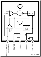
The meaning STR in this article for example is a Sanken regulator series and Fairchild series STR-F/G/W KA05Q Is an ic Quasy Resonant Flyback (QRF) Swiching Regulator comprising (a) control IC and (b) power MOSFETs that are packed into a single unit. The regulator is designed so that only requires a few external components. How it works : A. UVLO (under voltage lock out) Regulators will start working when the voltage Vcc start-up on pin-4 reaches 16V. Once the power supply voltage Vcc further work will be reimbursed through a switching transformer supplied from a diode rectifier. At the time the circuit was working when the voltage Vcc is less than 15V, the regulator controls will still work. regulator will stop working (protectionism) if the supply voltage Vcc drops to less than 11V.    2. Feedback control (pin-1) PWM regulators work using the system, wherein the output voltage B + to stable controlled by the feedback circuit of the output voltage B + >>> >...

Power supply with driver TEA1507

Image
Power supply with driver TEA1507 is mostly used by TV branded PHILIPS. Power Supply has an efficiency rate of up to 90% - thus requiring less cooling, as well as stand-by power required is less than 1 watt. Power Supply with TEA driver is equipped with a variety of surge protector that has a high reliability - not easily damaged if any part of a damaged power supply circuit and power transistor or FET heat is not easily damaged. Power supply circuits are dapatapat working on ac input voltage between 85 up to 275v. The way it works with the driver circuit power supply TEA 1507 is quite simple, so easy tracking of damage to the circuit. The picture above is the basic power supply circuit with TEA1507

How Regulator with 2 Photocoupler

Image
Working of Regulator with 2 Photocoupler that is : Photocoupler N901 - used as a coupling-off control on the regulator by mikrokontrol. Which is set high and low voltage B + (st-by at the B + voltage is low). Control of the pin-37 POWER mikrokontrol → V610 → VD913 V908 → N901. Photocoupler N903 - used to control on-off the regulator of X-ray circuit protector. X-ray protector circuit of flyback → VD451 → VD452 → SCR VS472. If the flyback voltage regulator over the job will automatically be turned off by N903 To disable the X-ray circuit protector, it can be temporarily removed photocoupler N903 first. In normal conditions the voltage at the transistor V474 should be zero. Regulator Schematics Trobelshuting there is no voltage for 5v st-by on the secondary : Disable by removing the first circuit protectors N903 Check the voltage of 300V Check all transistors Check the start voltage of 300V by R909 >> R906 to the base of transistor power regulator Check the feedba...

Different types of TV TUNER

Image
TV tuner that is used on older models and new models of television there are some differences. Therefore, understanding the different types of tuner would be useful if we want to replace the tuner with the other models. Supply voltage tuner. Tuner older models generally use a supply voltage of 12v, the new models are commonly used 5V supply voltage. Some use a 9V voltage, but very rare. TV TUNER Voltage Synthesizer tuner (VS tuner) Tuner that uses a tuning control (VT or BT) with a voltage between 0 to 33V Voltage Synthesizer tuner named. TV can be found on the aircraft models, old and new Based on how the control band-switch, Tuner VS then there are 2 kinds, namely Using 3-Band input sw, the VL-VH-U Using 2-Band input sw, the Band SW1 and SW2 Band. This tuner is actually similar to the type of band 3-sw. For control-sw 2 band is in the tuner will still be converted into 3-sw bands. Frequency Synthesizer tuner (FS tuner) or the type of PLL Tuner wherein the tuning voltage and the vo...

Vertical IC PIN-OUT DATA

Image
Vertical Vin = input (non-inverted), Vout = Vertical output, VfB = Vertical feedback (inverted inpput) Vcc to pump-up can be traced through the diode PUM-up and pump up Elco Capacitor VfB = or to Vin2 = Gnd or Vcc (-) Vertical IC PIN-OUT DATA AN5521 Vin = 4, Vout = 2, Vcc = 7, Gnd = 1, VfB = AN5522 Vin = 7, Vout = 5, Vcc = 2, Gnd = 4, VfB = 1 AN5539 Vin = 4, Vout = 2, Vcc = 6, Gnd = 1, VfB = 5 AN15525 Vin = 7, Vout = 5, Vcc = 2, Gnd = 4, VfB = 1 LA7832 Vin = 4, Vout +2, Vcc = 6, Gnd = 1, VfB = 5 LA7835 = 2 Vin, Vout = 11, Vcc1 = 1, Vcc2 = 7, LA7837 = 2 Vin, Vout = 12, Vcc1 = 1, Vcc2 = 8, Gnd = 11, VfB = 7 LA7838 = LA7837 LA7840 Vin = 4, Vout = 2, Vcc = 6, Gnd = 1, VfB = 5 LA7841 = LA7840 LA7845 = LA7840 LA7846 = 5 Vin, Vout = 3, Vcc = 7, Gnd = 2, VfB = 6 LA7848 Vina = 5, VinB = 6, Vout = 3, Vcc (+) = 7, Vcc (-) = 2 LA7876 Vina = 5, VinB = 6 Vcc (+) = 7, Vcc (-) = 2 STV9302 = see AN5522 STV9379 = See AN5522 TA8403 Vin = 4, Vout = 2, Vcc = 6, Vcc = 6, TA8445 Vin = 2, Vout = 11, Vcc1 = 1 ...

Vertical IC Configuration

Image
Various kinds of vertical out IC configuration.Ac coupling -connect from the yoke deflection output to a coil connected directly.Dc coupling - connected the output to the coil through a capacitor deflectioan yoke. Electrolityc Capacitors (usually worth 1000u/35v). This configuration requires two kinds of voltage (the voltage mirror plus-minus).Dc input coupling using diffferential - uses 2 input from the driver IC. Vertical IC Configuration AC Coupling Vertical IC Configuration DC Coupling

Understanding the workings of Vertical Deflection

Image
Vertical deflection parts, serves to provide a sawtooth current to the vertical deflection coil so that horizontal lines are generated by applying localized horizontal deflection from the top of the screen and moves towards the bottom of the screen. Sweeping PAL system has a vertical frequency of 50 Hz and 60 Hz NTSC system. Vertical deflection circuit there are several variation, is in contrast to the horizontal deflection circuit on television almost all the same. Broadly , the vertical deflection section comprises: Yoke Deflection Vertical oscillator (vertical countdown) Ramp generator Vertical amplifier drive Vertical amplifier-out Pum-up (flyback generator) Feedback circuit Vertical deflection coil Countdown vertical as the vertical oscillator . Vertical count-down got input from the horizontal frequency count-down and divide in order to obtain the vertical frequency. In this section there is a circuit called a "vertical window-counter" which serves to automatically ad...

Protectors Circuit on SMPS (power supply)

Image
The simplest example SMPS which still uses 3 transistors (C3807, A1015 and power transistors) classic problem that often occurs is: - Problem in the feedback circuit can cause the output voltage B + over so that it can endanger the aircraft as a whole. For example elco erupted, pcb burnt burnt by over-heated, horizontal transistor short. - Problem on feedback circuits may cause power regulator transistor is damaged due to over current transistor (eg, due to the 47k resistor transistor circuit on the secondary error detector value is delayed). - If the input ac voltage drops can cause the power regulator transistor is damaged, due to over current transistor If the secondary there is a power transistor short can cause damage over current regulator. - Protectors are designed to make the SMPS SMPS "reliable will not be damaged" if there are things that go wrong as mentioned above.  SMPS Circuit SMPS circuit using IC systems generally are designed with a surge protector, which inc...

X-Ray Protector Circuits

Image
A protector system that is applied at the beginning of the television technique, therefore most often found on old aircraft models. If the high voltage anode of the picture tube flyback tranfo exceed the permitted limit, the picture tube can generate x-rays from the anode and shadowmask are bombarded by electrons at high speed. To avoid this problem then mounted x-ray surge protector circuit , which automatically "horizontal section will be turned off" if the high voltage from the flyback over. X-Ray vertical protect The workings of x-ray protector: High voltage flyback sampled (generally taken from the pin-heater), rectified and is derived using a divider (devider) that uses a resistor-type high-precision resistor. Sample voltage is used to determine whether the condition is normal flyback voltage or over. A "zener diode" as a voltage sensor connected to the sample. In normal conditions the amount of the sample voltage is below the zener voltage of diode so that th...

TV Protect Circuit Dead or Damaged ?

Image
Television set equipped with a circuit protector, then there are several possibilities that could occur if there is a problem on one of the circuits. Protect circuit horizontal part - When turned on the horizontal plane will live for a while, but then died again. At the time of death when measured on the horizontal driver indicates that no drive signal. If the power jack unplugged then try to turn on again then repeated a similar incident will happen again. But if if the base of the transistor or transistor try to open removable drive signal was viable. Protect circuit of microcontroll - If checked the voltage at pin microcontrol power on-off control, power control is turned on when the plane going "on" for a while then back "off". If you unplugged the power jack will power "on" again, but briefly and then keep coming back "off". On certain models sometimes die when the aircraft was marked with the blazing LED indicators blink. Protect circuit tu...

STV9380 and STV9381 Vertical efficient

Image
STV9380 and STV9381 is a vertical ic-out which very efficient, so it does not require cooling (heat sink) as the vertical ic is generally. This circuit works the same way as most other vertical ic, except at the amplifier end only. Amplifier section works at the end of class D (this is different to the generally vertical ic which working on a class AB).  STV9380 and STV9381 Vertical signal input by the "MODULATOR" changed its form to first become a form of "pulses" box before it is reinforced by the end of the transistor. Here transistor "amplifier end" work as like "switching transistor". Output result is a strengthening of which pulses of the box is then returned into regular shapes such as vertical signal using an LC fillter (capacitor and filter coil) . Requires IC supply voltage (+) 16V and (-) 16V STV9380 is able to produce pulses of the vertical 2.5 APP (Ampere pitch to peak) and STV9381 3 APP. STV9380 and STV9381 Vertical efficient

SAMSUNG protect circuit with LA76931

Image
Following is the protect circuit Samsung TV which use IC LA76931 as basic working the protect circuit. This Protect Circuit LA76891 located at pin-30 whichconnected to the collector of transistor Q902.In normal conditions the voltage at the base of Q902 is "low" and the voltage at pin-30 is "high". For the temporary crippling protect, it can be removed Q902 (or to the emitter-base short). SAMSUNG protect circuit with LA76931 Sampling circuit protect from: Vertical Protect. Pulses of the vertical-out rectified by diode D355, so that the base voltage is approximately 0.6V Q904 ,and collector voltage is 0v. X-ray Protect (option). Sampled using a heater voltage of the circuit as shown below. Normal vltage in x-ray path to the base of Q902 is zero. ABL protect. If there is damage to flyback voltage which can cause a high rise ABL, then protect circuit will actively work.

How to check TV Flyback

Image
There are actually several kinds of tools that can be used for check whether flybak damaged. But we have a simple way we have always done for ascertain whether flybak damaged or is still good, before replacing the horizontal transistor. All it takes is a light bulb with an added Exciter 100Watt cable connection along approximately 25cm. The trick determine if flyback damaged or is still good is as follows : Break up the relationship between the collector of transistor horizontal flyback-out. By (a) Open collector aspirated by means of the printed board solder, or (b) Remove the jumper cables if any, or (b) Cutting prited path. Ac volt-meter pairs of horizontal transistor base with a ground out. Turn on the plane a little while - there must be an ac voltage of about 1v. This is done is for ensure that the horizontal oscillator and driver are working horizontally. Replace light bulb between the collector of transistor flyback horizontal (light diseri the collector). Turn on the plane...

TV Vertical Protectors

Image
Vertical Protectors (another term surge protector or Vertical CRT Neck Guard or protector) . If the vertical deflection does not work, then the raster will glow a horizontal line. This can cause the picture tube phosphor layer was destroyed by fire when the aircraft be kept alive in the long term. There are several types of system protectors, vertical relationships: Protector surge protector is connected with x-ray to the horizontal which will trigger the horizontal oscillator is not working Protectors gets connected to microcontrol that will trigger the "power off" so that the plane will turn off automatically or plane alive but raster becomes dark (brightnes level down). Vertical Protect The workings of the system-vertical surge protector that can be found there are several kinds: Using sampling pulses from vertical-out IC which is connected to  microcontrol  . If  microcontrol   not receive these pulses the surge protector will work. Using a sampling of...

The damage Horizontal LG TV

Image
Often find LG TV is switched off completely. After checking it Hor short TR / koslet so that all the inverter output voltage drop. Start with the appointment of TR page and check the voltage and turns back to normal. Do not always replace with a new TR because TR surely you will lose because they will surely be broken again, if immediate profits and normal life. After checking on the block capacitor Horizontal out that there was a rather plump and lifted it after it is dry there is no value of the capacitance. LG TV Capacitor is located on the collector TR Hor bypassed to ground which is parallel with the diode. For the slim LG 21 "inch typically use 2kV 183j (18n 2kV) for the black pearl 29" using 103j2kv (10N 2kV). After replacement of capacitor TSB and TR Hor who just started a TV and Direct TV was OK. 've Also found a balck pearl TV LG 29 "wide image conditions and so OSD is only half visible. As usual checks are still in the horizontal section. Initially thought...

IC LA78040 schematic for vertical deflection

Image
Synchronization circuit to make the signals useful in the process of scanning of the transmitter and sent to the Vertical and Horizontal. To be able to produce images on the picture tube phosphor surface is the same as what was sent, then the necessary adjustments to correct with ualsan which has decomposed on the sender and receiver on the review must be made ​​again, and this is called synchronization. Click to view larger On TV transmitter switching pulses that have made ​​the same frequency as in the reviewing, and by using the switching pulse is then mulapenguilasan point getter on the tube and picture tube can be adjusted simultaneously.  At the transmitter, each end of the line reviews one pulse is emitted horizontally, and also at each end of the line vertical review (this is called a field review), another pulse is emitted. At the receiver using switching pulses had the time of the beginning (start) review can be arranged horizontally and vertically. Switching pulses are c...

Treatment LCD monitor

Treatment LCD Monitor. At this time computer use familiar and already widely used either for work or entertainment. And of course when talking about computers it will not be far away with a device called a monitor. And today use CRT monitors have started to decrease with the LCD Monitor that despite having a price that is quite expensive but have many advantages than conventional CRT monitors. Here are a few advantages of LCD monitor is a stylish design, flat screen and a brighter color than convex or crt monitor screen, while also LCD Monitors have many advantages among which have a high resolution so that it can help many people especially those working Visual design field. There are some special treatment for LCD monitors in this case is for the treatment of LCD monitors, the following are some steps steps: Use the LCD as needed, Do not use if you do not need so-necessary and do not use it 24 hours nonstop jedanya have no time for any electronic item there during his lifetime (Lifet...

Switching Mode Power Supply using STR

Image
Switching Power supply circuit produces a voltage B + (dc voltage) needed television series taken from the net voltage household. G7 G7A chassis and power supply circuit using cool / cold in which the primary and the secondary power supply electrically separated so that the chassis can be directly connected to another device via an audio video terminal. Switching power supply This power supply circuit is a type SMPS (Switching Mode Power Supply) using mosfet transistor integrated circuit voltage controller in one IC package, namely STR-W6654. This IC will control the duty cycle of time off Vth2 Mosfet transistor to control the output voltage. Besides, the IC is also equipped with a safety circuit against overvoltage (OVP), overcurrent (OCP) and over temperature (TSD) circuit is working on 220V ac voltage with the input ac voltage range of 176V to 260V ac or known by the Wide range Regulators. How to Work Series Initial bias voltage dc pin6 IC801 obtained from an ac voltage through D811...

Audio amplifier with IC AN7522, AN7523 and TDA2616

Image
The series of amplifiers that are used on the television audio, amplifier used amplifier ICs, including the IC: • AN7523 • AN7522 • TDA2616 Third series of the function with the same system, namely BTL (Bridge Transformer Less). By using such configuration we get several advantages, namely no use coupling capacitors or coupling transformers. Block diagram of circuit in the IC AN7522, AN7523 and TDA2616 as in the image below : Schematic AN7522 AN7523 amplifier schematic Schematic TDA2616