Posts

Showing posts with the label Input output signal

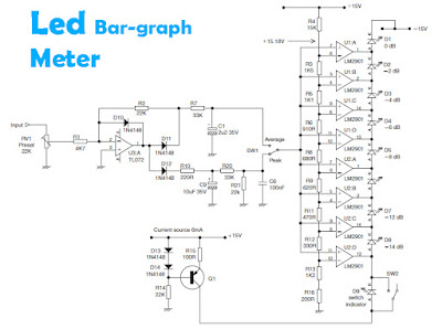
LED bar-graph meter circuit
Image
Several LED above and other components used to determine the signal amplifier, when in a state of high and low . If the signal received from the amplifier circuit is high then the LED lamp are lit up everything and more bright LED lamps, but otherwise if the received signal is low then the lights on only one or two , even absent or faint. To use the circuit you can connec with the output amplifier or speaker output , if there is reinforcing the other in the amplifier , can be connected to the output.

Very Simple Peak Indicator Circuit

Image
This series is made to indicate that the amplifier has been given the maximum signal, the amplifier has the ability to be at its peak. if the lights do not mean the signal-plus volume.the way it works is the LED lights will light up when given a signal that more than 1.8 volts, the average amplifier will be saturated (maximum) if the signal was given more than this.  The circuit is very simple to the point that we forget that making a series of peak signal can in this way. circuit is mounted on the output tone control IC, master mixer output, or input power amplifier. This series does not impose on other circuits.survived the experiment!

High impedance balance output circuit

Image
Because of high input impedance required to maximize CMRR, High impedance balance output circuit shown in figure below , has been used for the input impedance is determined solely by the input bias resistance R1 and R2. High impedance balance output circuit also useful for interfacing with valve equipment in the strange world of retro-hi-fi. High impedance balance output circuit Adding the output cathode followers for valve circuits are expensive and consume a lot of extra energy, so that the output is often taken directly from the anode gain-stage, as a result, even loading bridge the so-called 10 k distortion can seriously endanger performance and output swing available from the source equipment. All balanced phase dealt with until now have their input impedance is determined by value input resistors, etc., and this can not be raised without lowering the noise performance. High impedance balance output circuit diagrams above shows one answer to this. Input op-amp itself is quite a lo...

Low-Noise operational amplifier.

Image
Low noise balanced input is can also call for the circuit schematic above , because it has a very small noise output and balanced on each input . The noise output is only  117.0 dBu, its very small maybe even not at all out noise. The schematic based on IC5532 , to maintain ic remain good and avoid damage, you should install heatsink in every IC. If the circuit is finished and ready to use, then connect circuit in final befor going out to other components . Because this circuit is also suitable as a buffer amplifier.

High-pass and low-pass filters

Image
Subsonic and ultrasonic filters can be combined into a single circuit for more stable and orderly bandwith. This good and qualified for only two frequencies with the rotation of widely separate. Circuit schematic above shows the rotation of the scond-order or high-pass Butterworth filter in combination with secon-order low-pass filter. Part List : R1___1K R2___1K R3___12K R4___24K C1___4n4 C2___2n2 C3___470nF C4___470nF IC___IC op-amp For the capacitor , use the ceramic capacitors .