Posts

Showing posts with the label Audio

STK 4050 - 200Watt Power Amplifier Circuit

Image
Amplifier circuit with IC STK is tough and good quality. In this article an amplifier circuit with IC STK another base. Power "Amplifier 200Watt By STK4050" is an audio amplifier of the STK family with 200Watt power. To create a power amplifier with the STK4050 IC is not require many external components. Power Amplifier uses symmetric 30Volt power supply system. Power Amplifier With this STK4050 can reproduce the power 200 Watts at 8 Ohm load spaker. In making Power Amplifier 200Watt With this STK4050 do not forget to provide adequate heat sink for the IC STK 4050 in order to avoid overheating. Schematics Amplifier STK4050-STK4046 PCB Layout Amplifier Series Power Supply for Power Amplifier 200Watt By STK4050 been displayed in one image with a series of "Power Amplifier" 200Watt With STK4050 above. IC STK 4050 in this series there are several types on the market including STK4050II, STK4050V and STK4050. And below is a list of STK ICs are u...

LM1875 | 20 Watt Audio Power Amplifier

Image
20 Watts Power Amplifier circuit can be made ​​with an IC power amplifier LM1875. IC LM1875 is a single chip power amplifier from National. 20 watts audio amplifier with LM1875 is a low power amplifier with good quality to the room. To assemble the amplifier 20 watts with IC LM1875 component is not needed much support. 20 watts power amplifier using LM1875 IC in this article using symmetrical power supply. The virvuit of 20 watts audio power amplifier with IC LM1875 can be used as an experiment or first project for the reader, because it is simple and assembly of high success. Schematic Amplifier LM1875 LM1875 amplifier circuit with the above may result in the strengthening of the voltage up to 27dB for each channel (1 channel 1 IC). Strengthening the voltage can be changed by changing the feedback that is R5 R (on the circuit above using R 22K). But the tension reinforcement can not be less than 20 dB because it can cause oscillation. For the power supply or power supp...

10W audio power amplifier with bass boost

Image
As the amplifier circuit also uses a number of frequencies to drive the loudspeaker, the bass frequencies will be reduced. Therefore need to be plugged the bass-boost control at fedback loop amplifier, this is done to overcome the decline in quality. Graph bass can reach a maximum at +16.4 dB @ 50Hz. This circuit can be connected directly to the CD player, tuner, and tape recorders. Q3 and Q4 must be in pairs with a heatsink. Adjust the volume control at minimum position and R3 with a minimum value of resistance as well. try enabling circuit R3 da set up to read the flow of about 20 to 25mA. Wait for 15 minutes, connect the ground at J1, P1, C2, C4 C3dan. Connect also C9 at the output ground. For his series of power supply you can use the following scheme that fits perfectly with this amplifier.

High-power amplifiers

Image
By organizing the annual CES 2010, Pass Laboratories has recently introduced a new device that is X260.5 mono-block power amplifiers. X260.5 offers a power output of 260W and comes with the Super-Symmetry topology features that can improve performance by adjusting the characteristic value of balancing and damping amplifier distortion / interference. X260.5 device brings all the sonic advantages of mono-block operation for A / B high-power amplifiers in a physical package that can be managed device is half the physical size and weight of the device X600.5 Class D mono-block power. Simple physical size, weight that can be managed and high strength coupled with great performance make this device as the Pass Laboratories ideal power-amp in any system that refers to a 2-channel and multi-channel format. In addition, it also brings flexibility X260.5 combination for consumers who already have a device Pass Laboratories Stereo amp and want to add an additional channel pow...

BTL Stereo Amplifier TDA7052 / 3

Image
This is BTL stereo power amplifier with basic amplifier on IC TDA7052 / TDA7053

Condenser Pre Amplifier LM 1458

Image
This is a simple preamplifier circuit for electret condenser microphone. using a LM1458 dual op amp IC. The circuit takes the audio signal rom the condenser microphone and amplifier it, so you can use the microphone as the input to some device which wouldn’t normally accept microphone level signals . Schematic Circuit of Microphone Electret Condenser Pre Amplifier The circuit requires a 6-9 volt supply. Output of the microphone amplifier can be made variable by connecting a 10kΩ potentiometer . Circuit’s gain can be increased by men perbesar the value of 47K, depending on the input sensitivity of the main amplifier system. The microphone should be housed in a small round enclosure. List componet of condenser pre-amp mic circuit Q1,Q2    : LM1458 Op-Amp R1,R2,R3 : 4.7k ohm resistor R4, R5   : 10k ohm resistor R6,R7    : 47k ohm resistor C1,      : 0.22uF ceramic capacitor C2       : 1uF ceramic capacitor Absolute maximum ratings of L...

TDA2005 2 X 20 Watt Power Amplifier

Image
This time, there is a series of audio amplifer 20W as well, but using IC TDA 2005 as a series of his base amplifier. The series of 2x20 Watt Audio Power Amplifier using TDA2005 can you see in the picture below. Technical Data: Performance of TDA2005M: (for this circuit); At 4.14 V supply voltage: 2 x 20 watts (stereo) into 4 Ohms. Distortion: Approx. 0.2% at 4 Watts into 4 ohm load. Frequency Range: Approx. 20 Hz to 22 KHz. Input Sensitivity: Approx. maximum 150 mV rms. . Power supply: + 8 to 18 volts, approx. 3.5 Amps maximum per channel.

Mini Amplifier with 3 Transistor

Image
Mini 3 transistor amplifier is a simple amplifier with 50mW power drawn by 3 transitor. The series of three mini-amplifier transistors can be used for loud speaker 8 ohm load. Source voltage required to activate the mini-amplifier can be drawn from the batteries 9V.Rangkaian 3 transistor amplifier is often used in simple portabe audio devices such as radios or small tape recorder. Mini-transistor amplifier circuit 3 is quite simple as shown in the figure below. Mini-transistor amplifier circuit 3 includes type of amplifier OTL (Output Transformer Less). Mini-transistor amplifier circuit 3 is used for output coupling capacitors. Amplifier circuit is simple and suitable when used for audio amplifier experiment.

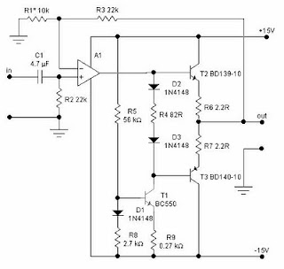
Class A headphone amplifier

Image
Class A headphone amplifier Class A headphone amplifier

Turbo Bass Circuit

Image
Turbo Bass Circuit Turbo Bass Circuit

HiFi Headphone amplifier

Image
HiFi Headphone amplifier HiFi Headphone amplifier

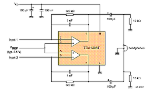
TDA1308T Headphone amplifier circuit

Image
TDA1308T Headphone amplifier circuit  TDA1308T Headphone amplifier circuit

Headphone amplifier circuit

Image
Headphone amplifier circuit with op amp ic OPA134, 2134, NE5532, 5534. Headphone amplifier circuit with op amp

TDA7294 150 W Power Amplifier

Image
This is power amplifier based on IC TDA7294 with output power 150W with 8 ohm impedance, source voltage + - 25V. for circuit see image below. TDA7294 Power Amplifier

200W power amplifier complete power supply

Image
This 200W power amplifier circuit using IC STK 4050. STK 4050 is a power amplifier module is very powerful, because the IC is already a module then only needed a little extra components to build a reliable 200W Power Amplifier. Here is a picture series of Power Amplifier ICs 200W use STK 4050 complete with its power supply:

Reducing Treble tone circuit

Image
Treble reducer circuit above is an example of a simple circuit and is suitable to be used as experimental material and analysis of the workings of the circuit.  As I mentioned earlier the bass reducer series, this series actually has the same working principles with a series of bass reducer. Where these circuits utilize capacitors nature of the charge and discharge. The difference of the damping function obtained from the difference of the capacitor. If the series bass reducer series capacitors are mounted on the op-amp input lines, while in this treble reducer series capacitors are mounted parallel with the strengthening of the op-amp prisoners. Installation of this circuit has a parallel in the work analysis in contrast with the installation of the series on a series of bass reducer. The difference is that the installation of the series, so we URLs that are easy to understand how a wire working capacitors for high frequency signal, so with high frekuesni so automatic signal to be...

Police Sirine Circuit with IC 555

Image
The series of police sirens with 555 ic this is a series of sirens that utilizes two IC 555 as a pulse generator and producing shrill voice.  Both ic 555 respectively build the astable multivibrator circuit and generate output signals with different frequencies. It is intended to be used as one of the high frequency generator or a screeching sound and the other as a regulator of the swing from last shrill voice. If we observe the working principle of this circuit is very similar to a series of modulation fm. Where the shrill sound signal likened to a high frequency signal from the oscillator circuit and control signal swing is the wail of the information signal or input signals that will transmit. This is consistent with the shape of the output signal associated with the loudspeaker, which has an output signal frequency changes in the form of regular meetings wave tenuous. Actually a series of sirens could be simpler than if you use a 556 IC which is a dual multivibrator or equal t...

Loudspeaker Driver Circuit

Image
The series of loudspeaker drivers are electronic circuits that function to bridge between high-output circuit with a loudspeaker berimpedasi berimpedansi low.  Why this driver is needed so that the output voltage to be inserted into the loudspeaker is not impaired. Declining value of this voltage is very possible given the lack of rules regarding the distribution of voltage and resistance instead of parallel. Where every prisoner that is placed parallel with other prisoners or the inmates totally substitute for detainee custody is smaller than with individual prisoners themselves. For example, 10 ohm resistance 10 ohms paralleled with the prisoners would get custody instead of 5 ohms. Resistivity 10 ohm to 100,000 ohm paralleled the total resistance is 9.9990 ohms. So it can be concluded that the total voltage will always be smaller than the origin of each detainee. Then, with a decrease in resistance (only using a combination of resistors) or the impedance of the output terminals ...

Condenser Pre Amplifier LM 1458

Image
This is a simple preamplifier circuit for electret condenser microphone. using a LM1458 dual op amp IC. The circuit takes the audio signal rom the condenser microphone and amplifier it, so you can use the microphone as the input to some device which wouldn’t normally accept microphone level signals . Schematic Circuit of Microphone Electret Condenser Pre Amplifier The circuit requires a 6-9 volt supply. Output of the microphone amplifier can be made variable by connecting a 10kΩ potentiometer . Circuit’s gain can be increased by men perbesar the value of 47K, depending on the input sensitivity of the main amplifier system. The microphone should be housed in a small round enclosure. List componet of condenser pre-amp mic circuit Q1,Q2    : LM1458 Op-Amp R1,R2,R3 : 4.7k ohm resistor R4, R5   : 10k ohm resistor R6,R7    : 47k ohm resistor C1,      : 0.22uF ceramic capacitor C2       : 1uF ceramic capacitor Absolute maximum ratings of ...

3 channel audio mixer

Image
3 channel audio mixer is built using some of the transistor amplifier. 3 channel audio mixer circuit uses voltage 9VDC summber which can supplied from a battery. 3 channel audio mixer circuit is designed special for the purposes of this Public Amplifier. Because the audio circuit of this mixer is designed specifically for the purpose of a portable mixer for audio public then this series has only a volume control without the tone control. Image series that looks below audio mixer is a series of mono, if you want to make a 3 channel stereo audio mixer it is necessary to make 2 pieces of a series of three channel audio mixer terebut. For more details, a series of three channel audio mixer can be seen in the following image. 3 channel audio mixer circuit Sign Component Audio Mixer With 3 Chanel Transistor P1, P2, P3 = 5K R1, R11, R15 = 180K R2, R12, R16 = 2M2 R3, R13, R17 = 750R R4, R14, R18 = 1K R5 = 15K R6 = 220R R7 = 1.5K R8 = 820R R9 = 150R R10 = 100K C1, C6, C8 = 1μF-63V C2, C4, C7, C...