Posts

Showing posts with the label Tutorials

Troubleshooting STR IC Regulator Power Supply

Image
A. Unable to start. Can be caused by: No start-up voltage supply Vcc or a voltage less than 16V Electrolityc Capacitors supply voltage Vcc filter dry.    2. Led indicator blinking If the supply voltage Vcc examined rocking. This is because the regulator of life and death because OVLO work., Die-protectionist regulators and auto start life over and over. If it is turned off Electrolityc Capacitors  usually still keep the rest of the cargo. Can be caused by: Electrolityc Capacitors supply voltage Vcc filter on a pin-4 dry. Replace with a value equal to or slightly larger. - triger UVLO input filter capacitor on pin-1 feed dry behind the declining value - triger OLP Rectifier diode of the switching transformer is damaged (sometimes when examined with avo-meter looks like a still good) cause the supply voltage Vcc drops of the switching transformer (UVLO) Part damage or broken lines on the feedback circuit of the voltage regulator through B to photoco...
Workings of STR IC Regulator Power Supply

Image
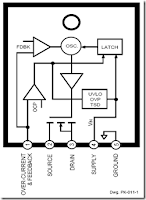
The meaning STR in this article for example is a Sanken regulator series and Fairchild series STR-F/G/W KA05Q Is an ic Quasy Resonant Flyback (QRF) Swiching Regulator comprising (a) control IC and (b) power MOSFETs that are packed into a single unit. The regulator is designed so that only requires a few external components. How it works : A. UVLO (under voltage lock out) Regulators will start working when the voltage Vcc start-up on pin-4 reaches 16V. Once the power supply voltage Vcc further work will be reimbursed through a switching transformer supplied from a diode rectifier. At the time the circuit was working when the voltage Vcc is less than 15V, the regulator controls will still work. regulator will stop working (protectionism) if the supply voltage Vcc drops to less than 11V.    2. Feedback control (pin-1) PWM regulators work using the system, wherein the output voltage B + to stable controlled by the feedback circuit of the output voltage B + >>> >...

Discharge the large electrolytic capacitor load

Image
If the switching regulator fails to work or fail to start, then it is usually of the electrolytic capacitor is storing charge. There are habits of some engineers dumping electrolyte capacitor like this using solder. This is actually a poor habit. Because without them knowing things like this sometimes can lead to broken solder element. Why this may happen? Note that the voltage on the electric charge of the electrolyte capacitor is 300V. While working voltage 220v only solder element. If the charge on the electrolytic capacitors are still full and the 220u electrolytic capacitors or more then this electric charge can only damage the solder element. Another bad habit of throwing of the electrolytic capacitor is to download shortkan legs electrolyte capacitor with a screwdriver. It is no possibility of damaging electrolytic capacitor itself, in which connection leg electrolyte capacitor is no risk in it will burn. How should the dumping of the electrolytic capacitors ? Alw...

Track the damage capacitors elco with ESR meter

Image
All technicians must have the same experience that the old models of aircraft generally have several common Elco its dry or down in value, mainly found in many brands of china plane. Eco is dry can cause a variety of disorders that are sometimes difficult to trace or even be able to make certain parts do not work at all, especially if used on a circuit that works at such high frequency SMPS (Switch Mode Power Supply) and the horizontal. Elco dry technicians sometimes make headaches and time consuming when you track the damage. Many technicians get around this problem by directly replacing all existing Elko, the Elko-regardless of whether Elko is corrupt or not. It is generally quite successful. But sometimes the quality is not good substitutes Elko, so the damaged aircraft back after use for some time. Replace all of Elko is also a problem for yourself if the circuit is improved a lot using Elko. The use of ESR-meter proved to be the most appropriate choice to solve the above problems....

Diode recovery time

Image
Understanding the parameters of "diode recovery time" .For prospective technicians are still learning and inexperienced, they generally recognize only two kinds of parameters of a diode, namely: The maximum working voltage (bias voltage when he gets back - or when not deliver - or when "off") The maximum operating current (when he gets a forward bias voltage of - or as leads - or when "on") Fast  Recovery diodes A similar experience we had some twenty years ago when a new SMPS first introduced on the television. When there is a diode voltage B + is broken. And then we replace the diode from the outside (our point of diode being sold in stores, rather than the official service) diode turns hot and soon broken. We think that the replacement diode voltage or current is less bulky. Then after replacement with a larger, but the result remains the same damage. Finally we order the diode with the same part number, and when the part arrived and was installed wrong...

How to check TV Flyback

Image
There are actually several kinds of tools that can be used for check whether flybak damaged. But we have a simple way we have always done for ascertain whether flybak damaged or is still good, before replacing the horizontal transistor. All it takes is a light bulb with an added Exciter 100Watt cable connection along approximately 25cm. The trick determine if flyback damaged or is still good is as follows : Break up the relationship between the collector of transistor horizontal flyback-out. By (a) Open collector aspirated by means of the printed board solder, or (b) Remove the jumper cables if any, or (b) Cutting prited path. Ac volt-meter pairs of horizontal transistor base with a ground out. Turn on the plane a little while - there must be an ac voltage of about 1v. This is done is for ensure that the horizontal oscillator and driver are working horizontally. Replace light bulb between the collector of transistor flyback horizontal (light diseri the collector). Turn on the plane...

How to choose the best for your home theater system

Image
Watching movies is a neat escape from the stressful lifestyle we live in. Watching movies in a wide screen and surround sound take you far away and into the movie scene you are watching. You watch it as if you were there in the movie scene. Of late, we can only experience this escape in a cinema. However, modern technology may be able to provide this same sight and sound experience right in your own living room. We will discuss the basic components of a home theater system in this article. Read on to understand how these basic components can deliver the best cinematic experience to a home theater system. Home theater experts state that the most important consideration in setting up a home theater system is the size of the room where you will set up the home theater system. The most important component of the home theater system, which is the television, is dependent on the size of the room. Although, the recommendation is 27 inches television set at a minimum is necessary for your home...

Type of Capacitor

Electrolytic - Made of electrolyte, Aluminum electrodes are used by using a thin oxidation membrane - Polarized capacitor - Cheap, readily available, good for storage of charge (energy) availablein very small or very large values in μF- Not very accurate, marginal electrical properties, leakage, drifting, not suitable for use in hf circuits Tantalum - Made of Tantalum Pentoxide. They are electrolytic capacitors butused with a material called tantalum for the electrodes. Superior to electrolytic capacitors - Nonpolarized capacitor - Excellent temperature and frequency characteristics,lack of current-spike-noise. Small size fits anywhere, reliable, most common values readily available. - Expensive, easily damaged by spikes Polyester Film - This capacitor uses a thin polyester film as a dielectric. - Nonpolarized capacitor - Not as high a tolerance as polypropylene, cheap, temperature stable,readily available, widely used. Tolerance is approx 5%...

The parts of the Speaker

Image
Basket (frame) Made of a metal plate that will support all parts of the speaker where the speaker of the other speakers can be attached to the intact  Magnet Here is used to generate a magnetic field of permanent magnets to be used to drive the voice coil, so as to produce sound. Parts of speaker Voice Coil Voice Coil is an important part of a speaker. Voice coil consists of Robbin (where rolled coil) and coil (the coil BWR - Brass Wire Rope), Coil is going to move in accordance with the signal diterirna. Spieder or Damper Spider or suspension dampers are used to speakers that serve to dampen the vibrations of the voice coil, so the voice coil can move freely. Cone Paper Paper Cone is part of the suspension of the speaker who serves simultaneously as an amplifier of vibration caused by the voice coil so it can form a clear voice signal received from the speakers. Dust Cap Dust Cap serves to channel sound vibration with paper cone and protect the inside of the speaker (where the air...

Solve buzzing and noise on the amplifier circuit

Power amplifiers that we sometimes raises a raft of small drone as groundingless than perfect.The following are some ways to cope with the hum of the power amplifier:  1. Keep sensitive circuits of the transformer, casing dimensions are not too small.One blog even suggested to use two-bok, bok special one for the transformer. For the toroid transformer or amplifier with a large transformer, should only contain a series of power amps, with no tone control.  2. Change the position of the transformer, side by side into the lower side (the transformer is high) withfacing a series of sensitive posts  3. Use a spacer on each PCB board as high as half the height of the transformer, eg as high as 2.5 cm or more so that the PCB board parallel to the core / center of the transformer, here the effect of the weakest fields.  4. We recommend using a stereo module instead of two mono modulesThis avoids wiring errors. If forced to, try to sizecable between the right and left m...

Tips and Tricks on Audio Power Amplifier Circuit

Amplilfier power series from the beginning until now did not experience any changes. Some say this series is good, but the series was good fitting assembly and tested the results are not as we expected. The problem is usually treble is less subtle, less sound, sound breaking, buzz, middle of the field tested the bass sound is lost. so you do not have to believe what people 100%. The quality amplifier built-up would differ greatly with the amplifier assembly, a series can be the same but the quality will depend on who manufacture it. Here are a few tricks to try How to cope with a buzzing sound Power amplifiers are often used in the field blazer. This circuit is said said person is a bell assembly. But you do not immediately interested in this power, the circuit rather complicated and difficult to understand reflect the intelligence of people who first mendisainnya. In my opinion a great power is the power of simple, inexpensive, easily assembled and rational. You do not need to use exp...

Improving Performance Bass Guitar

1. Replace strings: strings are the source of the sound of a bass. If bad strings, of course difficult to get a good sound. How good / expensive any bass, if strings are mendem ("dead") would sound so bad 2. Know your bass character of us, whether inclined treble, middle, or ngebass (low). From here our reference point. If soundnya not in accordance with our desires, try to correction with tone control / equalizer. 3. There are so many factors affecting the bass sounds, ranging from strings, pickups, body wood, neck & fingerboard. Try to identify the character masing2, eg the influence of wood types, pickup types, etc.. From there we can determine which one should be modified. Chain audio a bass sound as follows Strings-> pickup-> Preamp / Tone Control-> Connection Cable-> Amplifier Well, just select which one would aja in mod. Actually the material (wood) body / neck / fingerboard also influence: String-> Body/Neck/Fingerboard-> Pickup-> Preamp / Ton...

How to create a simple adjusting volume for amplifier

Image
This circuit usually used for amplifier that do not require additional device in one box amplifiers. Enhancements such as Equalizer , Tone Control , Mixer , etc.  Only by requiring a potentiometer mono or stereo if stereo power amplifier , and few  cables you can make this circuit easily. See picture below :    First connect the cable from the power amplifier input to pin2 potentio , and connect ground to pin 1 , then connect the output of tuner or other media player to pin 3. Try turning to the right then the sound will be high , and if played left back then the sound will below.