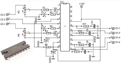
Stereo Low power audio amplifier circuit

Stereo Low power audio amplifier circuit og Audio amplifier has a power output of 2 x 2.3 Watt, which uses IC KA2206, KA22061, LA4180, LA4182, LA4183, LA4550, LA4555, LA4558. The required voltage for at least 6 volts to 13 volts DC maximum. Component takes is a ic that I mentioned above one of them, and several capacitors elco. This Schematics low power amplifier Component Description Stereo Low power audio amplifier circuit C1 = 1uF C2 = 100uF C3 = 100uF C4 = 100uF C5 = 0.1uF C6 = 470uF C7 = 1uF C8 = 100uF C9 = 100uF C10 = 100uF C11 = 0.1uF C12 = 470uF ICs can use the ic which I mention above for each ic datasheet can be seen itself.