Posts

Showing posts from February, 2012

Audio Peak Indicator Circuit

Image
The existence of the peak indicator "Audio Peak Indicator" in an audio device is needed. Audio Peak indicator is a simple circuit to detect the peak level of audio signal. Audio Peak indicator circuit is built with duabuah transistor and LED indicator as peak level detection of audio signals. The main function of a series of Audio Peak indicator is to determine the occurrence of the peak level of audio signal that is more than +4 dB, equivalent to 1.25 V rms. If the received audio signal Audio Peak Indicator more than +4 dB was the LEDs in series Peak Audio This indicator will light. Audio Peak indicator circuit is mounted on the output audio system. Audio Peak Indicator Component List: R1 = 10Kohm R2 = 1.2Kohm R3 = 220Kohm R4-5 = 4.7Kohm C1 = 47uF 25V C2 = 2.2uF 25V Q1-2 = BC550C D1 = LED RED We hope to form the reference materials in the manufacture of circuit pernagkat Audio Peak Indicators in the audio readers.

Timer with about 10 minutes

Image
Applications of 555 timer IC is very diverse, one series of 10 Minute Timer with IC 555. 10 Minute Timer This circuit uses IC NE555 is set as a monostable multivibrator. The timing of the timer circuit 10 minutes with the IC 555 is governed by the configuration of C2, R4 and R5. The greater the value of C2 at 10-minute timer circuit with IC 555 timer is active then the time will stay longer.  Total resistance value between R4 and R5 also determine the active circuit 10 minute timer with IC 555, where the greater the value the longer time was also active. The core active setting the timer on the set of C2 charging time for 10 minutes on the timer circuit with IC 555. So, with the value of C2 remain so with time on the circuit timing Timer 10 minutes by IC 555 can be set by changing the resistance value R 4 + R 5. Indicators of active timer at 10 minute timer circuit with IC 555 uses the LED D2 and D3 will light up only one course to identify the active timer and the timer has not be...

Fire alarm with light sensor

Image
Fire alarm can be made with a light sensor (LDR) as in the article with the title of Fire Alarm with this LDR sensor. Principles of fire detection Fire Alarm with LDR sensor is to detect the presence of smoke through the LDR. LDR in the series Fire Alarm does not stand alone in detecting a fire, but the LDR in the pair with the light shining on the LDR. Hence, in the detected smoke from the fire then the intensity of light received by the LDR LDR decreases and eventually trigger an alarm system on a series of Fire Alarm with this LDR sensor. Part 2 that in the series of Fire Alarm with Sensor LDR are some of the sensors, tone generator, audio power. Image Series Fire Alarm with Sensor LDR Function Section of the Fire Alarm with Sensor LDR Part of LDR and light sensor facing to fire smoke detection Part trigger using transistors and regulators as a trigger tone generator 7805 Tone generator section with IC UM66 Power audio section uses an audio power IC TDA 2002 which is equipped with v...

Powerful Battery Charger Circuit

Image
Series NIMH Battery Charger with IC LT4060 is a NIMH battery charger is powerful, effective and efficient. Featur owned by IC LT4060 is a specialization of a NIMH battery charger. NIMH Battery Charger with IC LT4060 can perform safely charging NIMH batteries because it comes with a battery temperature protection is in charge and the peak level detection system of the battery voltage is in charge.  Battery temperature protection system from the excessive use of NTC temperature sensor. Series NIMH Battery Charger with IC LT4060 also features a charging indicator that will light up when charging and will die when the battery is full. IC 4060 used in this NIMH battery charger from Linear Technology is a production that is designed special for NIMH battery charger. Image Series NIMH Battery Charger with IC LT4060 Description Series NIMH Battery Charger with IC LT4060 R2 potentiometer used for setting the maximum temperature (at set at the value of 4K) LED D1 is a battery charging indica...

74LS247 7 Segment Display Circuit

Image
The displayor using a 7 segment display in electronic device applications is drain port of a microcontroller or data that would point in the show, especially when the data would be displayed more than 1 digit. necessary path to control the resources of each 7 segment and the path to input data on the 7 segment.  Series Display 7 Segment 4 Digit Multiplex is a way to save the port or microcontroller data path that will be displayed. Series Display 7 Segment 4 Digit Multiplex uses BCD to 7 segment decoder 74LS247 BCD to encode data from the data that will be displayed, then for each resource viewer 7 segment using the set of transistors as electronic switches. Current flowing in the viewer in a series of 7 segment Display 7 Segment 4 Digit Multiplex is in limiting use yag resistor in series pairs in each collector transistor. Image Series Display 7 Segment 4 Digit Multiplex Configuration circuit components 7 Segment 4 Digit Display Multiplex The legs LT, RBI, RBO in this circuit is n...

PWMMotor Driver

Image
As the title "PWM DC Motor Driver with Forward / Reverse and Breaking" this series is a PWM DC motor controller that can control DC motors with clockwise rotation and counter-clockwise and is equipped with a braking system.  In a series DC motor control PWM DC Motor Driver with Forward / Reverse and Breaking use this system for SASL PWM DC motor rotation speed. Power driver in a series DC motor PWM DC Motor Driver with Forward / Reverse and Breaking uses mosfet IRF150. Then, to control the direction of rotation of DC motor in the circuit of PWM DC Motor Driver with Forward / Reverse and Breaking uses relays. Then the braking system on a series of PWM DC Motor Driver with Forward / Reverse and Breaking is done by a resistor that is connected to the motor using relays. Fig circuit PWM DC Motor Driver with Forward / Reverse and Breaking Click to view larger See image details a series of PWM DC Motor Driver with Forward / Reverse and Breaking above. DC motor speed is set to pulse...

Zero Crossing Detector Circuit

Image
Zero Crossing Detector circuit is basically an application of a comparator. In the article series Zero Crossing Detector with Op Amp is built using a comparator of an Op Amp IC741/351. The process of detection of this comparator is  0Volt input signal crossing point by making reference value at comparator 0Volt.  The output of the Zero Crossing Detector circuit with Op Amp is wave-shaped box that detection result of the crossroads of 0 volt input signal.

Atmel microcontroller-Easy Downloader Circuit

Image
Easy Downloader Circuit Atmel microcontroller series AT89Cxx51 Easy Downloader is one of the downloader that is often used to write data to program the Atmel microcontroller AT89CXX51. Easy Downloader AT89Cxx51 ATMEL microcontroller is using the serial port as a channel of communication with the computer.  Easy Downloader ATMEL Microcontroller AT89Cxx51 can be used to program Atmel AT89CXX51 in parallel. Atmel microcontroller series AT89Cxx51 Easy Downloader is quite simple to make your own because the components necessary to membutanya not complex. Atmel microcontroller series AT89Cxx51 Easy Downloader do not support the serial programming microcontrollers ISP. In the article Easy Downloader ATMEL Microcontroller AT89Cxx51 only displays images Easy Downloader Microcontroller series from Atmel AT89Cxx51 only and are simple.

AT89C2051 microcontroller circuit

Image
Real time controller AT89C2051 Real time controller is a device used to exercise control over household device continuously ongoing and scheduled. The series of Real Time Controllers with microcontroller AT89C2051 which dituls in this article is a tool that can do that serve targeted. The series of Real Time Controller with Microcontroller AT89C2051 Atmel AT89C2051 uses a data processor and controller as device installed.  In the application directly devices requires a separate interface from a wide range of Real Time Controllers with this AT89C2051 microcontroller. When will connect the device with the AC power source to use interface optocoupler (MOC) or solid state relay. Devices that can be connected with the series of Real Time Controller with Microcontroller AT89C2051 include lights, water machines, fans, electronic gate. The series of Real Time Controllers with this AT89C2051 microcontroller to control a height of water level, controlling the flame lights the scheduled SCARA...

SMS Remote controller circuit

Image
SMS Remote controller is a device used to control a device remotely using SMS through GSM mobile phones. Process control equipment with a series of AVR ATTiny To SMS Remote Controller can be used to control life and death of these equipment will provide information on the status of replies to our phone in return successful command execution.  Equipment can be controlled by a series of AVR ATTiny To SMS Remote Controller include lights, water pumps, garage doors, gates and much more. AVR series ATTiny To SMS Remote controller uses the module-47 Sony ericson GM as recipient and sender of the SMS module. Then to the SMS data processor on a series of AVR ATTiny To SMS Remote controller is using AVR microcontroller ATTiny 2313. Series AVR ATTiny To SMS Remote Controller SMS Remote controller circuit Click to view larger.  AVR circuit this part ATTiny To SMS Remote Controller AVR series ATTiny To SMS Remote controller uses the AVR attiny2313 with 4MHz clock frequency, GSM Modu...

Flip Flop Led Circuit

Image
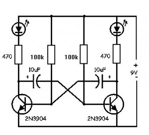
Flip Flop LED Flip flop circuit is a series of free runing multivibrator given the burden of LEDs on each side of the transition changes its output signal. Flip flop circuit with LEDs is quite simple, that is prepared with 2 units and 2 units of 2N3904 transistor circuit tank circuit composed by the RC circuit.  LED indicators signal a change that is placed on each side of the flip flop will be lit in turn by the fire and extinguished the same as the charge and discharge capacitor. Flip flop circuit is quite simple as shown in the picture below. Flip Flop LED series The working principle is the flip flop over when the series voltage source is given then the 10uF capacitor will be charged through R 470 and the LED will then be forwarded to triger the transistor base so that the transistor will turn ON and LEDs. this occurs alternately on each side, so that the LED light will illuminate in turn as well.

Frequency to Voltage Converter Circuit

Image
IC LM2917 Frequency to Voltage Converter IC LM2917 IC chip is designed specifically as a Frequency to Voltage Converter or Frequency to Voltage converter. In its use to applications Frequency to Voltage Converter IC LM2917 requires few external components.  There are several examples of applications of Frequency to Voltage Converter IC LM2917 datasheet that is included in the LM2917 IC. In this article series Frequency to Voltage Converter IC also taken from the LM2917 datasheet. The advantages of single chip LM2917 Frequency to Voltage Converter is able to provide instantaneous volt output o at time of frequency change 0 Hz. Very easy to apply in measuring the output frequency with the formulation of single-chip Frequency to Voltage Converter VOUT = FIN x VCC x R1 x C1. Then the single-chip LM2917 Frequency to Voltage Converter This configuration requires only the RC only in frequency doubling. And has an internal zener regulator to aimlessly accuracy and stability in frequency-to...

Battery Charger based on AVR ATMega 8535

Image
Battery Charger in general can be interpreted as a means to recharge the battery charge. Principles of good charger circuit is capable of providing resources to perform effectively charging the battery, efficient and safe. AVR-Based Battery Charger ATMega 8535 With LCD Display This is an idea that had just emerged from the author. In AVR-Based Battery Charger design ATMega 8535 With LCD Display is using AVR microcontroller processor charger with ATMega 8535, process the data viewer charger with LCD, a safety from a hot temperature with the temperature sensor LM35 and several buttons for setting the charger. And component power charger Battery Charger Based on AVR ATMega 8535 With LCD Display is a FET. Click to view larger Function-Based Battery Charger Part Series AVR ATMega 8535 With LCD Display ATMega 8535 AVR microcontroller serves as the controlling process of the charger. Button S1 - S5 as input data charger settings (setting the current, maximum temperature, peak voltage batterie...

ADC 207 Flash Converting

Image
Flash Converting - ADC 207 ADC 207 is the first to use Flash Converting An Advanced High Speed ​​VLSI 1.2 micron CMOS process. The process that is able to do the ADC 207 as mentioned earlier is very great and makes the ADC 207 is unique. The speed of the process of this ADC has a good linearity and have a stable temperature. ADC 207 has a lower power consumption is 250 mW. ADC is working with +5 VDC voltage source and at a frequency of 20 MHz. ADC 207 has a small sampling time is 12nS, thus making the ideal sampling results. ADC 207 has 128 features auto balanced comparators with each conversion that serves to offset temperature and dynamic effects that exist. Resistor ladder in the ADC 207 has a mid point that is connected to an external voltage source and function in the conversion of 7-bit linearity. ADC 207 has 3 levels of output that is easy to connect it with external components. ADC 207 Architecture Feature ADC 207 7-bit flash A / D Converter Sampling frequency of 20 MHz Low po...

Very Simple Peak Indicator Circuit

Image
This series is made to indicate that the amplifier has been given the maximum signal, the amplifier has the ability to be at its peak. if the lights do not mean the signal-plus volume.the way it works is the LED lights will light up when given a signal that more than 1.8 volts, the average amplifier will be saturated (maximum) if the signal was given more than this.  The circuit is very simple to the point that we forget that making a series of peak signal can in this way. circuit is mounted on the output tone control IC, master mixer output, or input power amplifier. This series does not impose on other circuits.survived the experiment!

DC fan control circuit for power amplifier

Image
DC fan control circuit for power amplifier .Variable speed DC fanThis series of works based on the input signal. Speed ​​/ fan rotation depending on size of the input signal coming from speaker lines. If there is no signal then the fan will spin slowly according to the setting VR1.Input supply can be taken directly from the main transformer power amplifier, 12V CT 12V, so no need to increase the transformer again. Circuit Schematic Electronics | CSE This circuit has been tested and do not cause buzzing.correction: the lowest R: 560 ohm

Solve buzzing and noise on the amplifier circuit

Power amplifiers that we sometimes raises a raft of small drone as groundingless than perfect.The following are some ways to cope with the hum of the power amplifier:  1. Keep sensitive circuits of the transformer, casing dimensions are not too small.One blog even suggested to use two-bok, bok special one for the transformer. For the toroid transformer or amplifier with a large transformer, should only contain a series of power amps, with no tone control.  2. Change the position of the transformer, side by side into the lower side (the transformer is high) withfacing a series of sensitive posts  3. Use a spacer on each PCB board as high as half the height of the transformer, eg as high as 2.5 cm or more so that the PCB board parallel to the core / center of the transformer, here the effect of the weakest fields.  4. We recommend using a stereo module instead of two mono modulesThis avoids wiring errors. If forced to, try to sizecable between the right and left m...

Tone control low noise circuit

Image
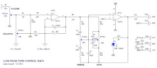
Tone control or pre-amplifier is an amplifier circuit supporters. Sometimes some of us do not know where a good amplifier, a raft alone and the results are not much different or even the same. Therefore we must know the character of the advantages and disadvantages of each amplifier equipment. Tone control low noise here does not mean without noise, but noise compared with the lowest tone control on the market, for example Ronica transistor 4, TL-084, TC-2 LM833 etc. CSE | Circuit Schematic Electronics Jump toexplanation of each component ... Potensio 1 serves to regulate the intensity / level of the incoming signal is assisted potensio 2 as balance / counterbalance. Potensio 2 is still installed and is usually an optional component. 1-2uF/250V capacitor R1 is actually a brand name,but I prefer to replace it with a 1K resistor / 5% normal for reasons to avoid hum and interference sensitive. R2 R3 while minimizing interruption to adjust the impedance OP-amp 1. R4 and R5 serves to increa...

Spirit Amplifier Schematics

Image
Amplifier circuit built-up is pretty nice not always complex. There are a series of amplifiers that I saw a picture of the kit immediately. The circuit is quite simple, there was the most complex in the pre-amp and its protector. Click to view larger | CSE-Circuit Schematic Electronics How a series of ...Op-amp stage 1 is the heart of the circuit, the input stage with enough power to drive the power transistor. Sensor1 ntc & 2 can be attached to the main heatsink, this is optional so it can be eliminated, its functions to lower the bias voltage value if the heatsink overheating. There is no bias trimpot, R6 and R8 instead divide the voltage so we get <= 0.6V at the base driver tr. If the voltage is just a little more driver transistors can be damaged and could trigger the final transistor is damaged in congregation / pairs. These transistors are used frequently broken, but after replaced by Sanken, safe. Thus the risk of the snaps without a limiter amplifier. A pair of Q1 & ...

USB SPDIF DAC with IC PCM 2902

Image
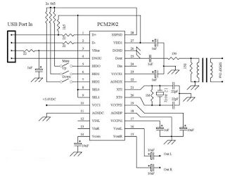
The tool that I made and I discuss in this article I give the name USB SPDIF DACEvery word in the name corresponds to the function of the tool that I made this. USB, this device serves to take the music information in digital form from a computer via the USB port SPDIF, this tool can output digital music information received through the USB port, through the SPDIF output terminal that is also present in this device, so if you have a DAC that does not have a USB input, you can still use and do not need to buy a new DAC that has an input USB. DAC, this tool can convert the digital signals derived from the USB port, an analog signal, which you can connect to the amplifier to the ahirnya you can hear the speaker Scheme of the USB DAC can be seen in Figure 1 below. Click to view larger. | Figure 1 As you can see on the schematic in Figure 1 above, which is the heart of the circuit is IC USB DAC PCM2902 made ​​by Texas Instrument, other than that I also added a digital SPDIF output isolation...

TDA 7309 Digital Audio Processor Circuit

Image
Digital Audio Processor TDA 7309 is a stereo audio processor with independent volume control of each channel was to get the audio quality of a good processor. Digital Audio Processor TDA 7309 is equipped with a loudness control is controlled externally. Digital Audio Processor TDA 7309 also has a soft mute feature stand-alone for each canals. Digital Audio Processor TDA 7309 is controlled via the I2C serial bus system with a microcontroller interface.  Click to view larger. Block Diagram of Digital Audio Processor TDA 7309Feature-owned Digital Audio Processor TDA 7309The input multiplexer with 3 stereo inputRecording function on the output lineLoudnes external ontrolIndependent volume controlDigital volume control with 1dB stepSoft MuteAll functions of the Digital Audio Processor TDA 7309 is programmed via the I2C serial bus system

Create a Digital Volume Control Circuit

Image
This series is the volume of the digital amplifier That is used on or tone control. This series ic type using DS1669 Digital Pot IC specifically for this volume match. a series of settings used at the middle-class amplifier That small powerless under 50 watts.volum11components: C1 = 0.1uf Ceramic, IC = IC DS1669 Digital Pot, S1 / S2 = digital swicthOr you can use the series to this one:volum2The Work: The digital volume control IC uses 9. Click to view larger. Required to operate the series voltage regulator is 12 volts. IC1 (555) is very good to work as a flip-flop. Frequency or period can be determined with selecting value of resistor R44, R45 is combined with a capacitor C6. In this series has a 0.3 second period.IC2 is used to Decrease or increase of the calculation. In the series of this mode is used to raise up and down mode is used to Decrease the volume.  While IC4 and IC3 has a 16-channel, analogue multiplexers, while working as an analog switch. IC3 is used as in the seri...

Create a electric shock-resistant tool

Image
You've electric shock?? .. Well, .. it was nice to recover all your gout! Sometimes true .. but we often do not touch circuit accidentally in the work that is still connected with line / grid (pln) .. pissed, wants I think we stepped on the stuff ..! patient first.  Is there any easy way to avoid electric shock in repair work .. can even avoid the occurrence of ESD, if we deal with electronic goods which are sensitive to ESD (PC motherboards, mobile phones, circuit digital etc). you raft just like this series .. used as supply for the solder, when dealing with components which are sensitive to ESD and touch (CMOS IC). the greater capacity of the transformer Ampere. the greater the (good) power which can be handled. The second transformer is identical / similar.

Make A Virtual Phone Battery

Image
Virtual cell phone battery is a replacement cell phone batteries for those of you who use the phone as a modem. Including myself, who use the phone as a modem HAIER d1200p internet.  Why must use this virtual battery. For those who surf hobby "full time" with a phone modem, would know the problem, the battery gets hot and fast reply wasteful even worn out. This tool is a good solution to keep and care for our cell phones from the possibility of damage from over-charging its battery.I created a virtual battery works as follows:We take the source of its power supply from the USB port because the port is very easy and simple to use and simply provide a standard current source when the phone is online (500-750mA). The workings of the circuit is as follows:Diodes or diode 2Amper in 5239 this standard to provide a useful addition to the polarity of the voltage which is also a component of protection against misuse. You can just use a 1 Amp diode (IN4002-4007). I use the IN 5239 is ...

IC LA78040 schematic for vertical deflection

Image
Synchronization circuit to make the signals useful in the process of scanning of the transmitter and sent to the Vertical and Horizontal. To be able to produce images on the picture tube phosphor surface is the same as what was sent, then the necessary adjustments to correct with ualsan which has decomposed on the sender and receiver on the review must be made ​​again, and this is called synchronization. Click to view larger On TV transmitter switching pulses that have made ​​the same frequency as in the reviewing, and by using the switching pulse is then mulapenguilasan point getter on the tube and picture tube can be adjusted simultaneously.  At the transmitter, each end of the line reviews one pulse is emitted horizontally, and also at each end of the line vertical review (this is called a field review), another pulse is emitted. At the receiver using switching pulses had the time of the beginning (start) review can be arranged horizontally and vertically. Switching pulses are c...

Building a radio station

Image
Requires us to make things systematically and efficiently, because time is very valuable to us, then some of the advances in technology has been applied in various fields, including education, because this is where all the technological advances developed.Lots of technology is rapidly expanding in our country today. With technology growing by leaps and bounds this is what will make the work more systematic and efficient.Based on our technological advances and his friends create a system are related to the Electronics course, we propose the same faculty to develop a community tool. We got a second job in four semesters, which makes the FM transmitter. Departing from hobby assembling electronic items, we try to assemble a mini-power transmitter that can emit a short signal of approximately 100 meters with power (power) 5 watts. This is a pilot who later became 12 watts. With 12 watts of power, radio broadcasts to reach a village.  1.2 Formulation of ProblemProblems are handled from t...

Boster 15 watt rd 15 no tune

Image
15 rd booster requires only 0.5 watts of input capable of out 15 watts, the voltage of 13.8 volts it needs. in this series are made to work freq 87-108 mhz fm broadcast. but did not rule to be modified in other freq. schematic and pcb layout to please download here  

Booster BLW 60

Image
In this post an opportunity, I upload booster BLW 60 which may be an inspiration to create home brew. Here I include a file layout that can be unlocked via software sprint layout. of course the software you can download here as well. ok g tuk need to talk at length, immediately wrote download the full data here

50 ohm dummy load

Image
Assemble their own 50 ohm dummy load with a capacity of 40 watts. first of all we need is a 1k resistor 2watt as many as 20 seeds, plain PCB, and also the female connector just as the picture above.The first step is the form of a round PCB with the above picture just as much as 2 pieces of 3 cm diameter, to which drilled the diameter of the connector.  With the goal as a PCB connector while the other will not need to be drilled due to the bottom.two pairs of resistors that is just as in the picture. if the test is finished living, 50 g 0hm what? if the resistor is not needed to be corrected again.What if want a bigger watt capacity, we simply replace the resistor, 1K5 ato 2k, of course, if using a 2k resistor smakin much we need. resistor which point no matter how much we want to attach. critical values ​​should be 50 ohms and the value of each resistor must be equal.survived the experiment may be useful

Filter freq dirty from an fm transmitter

Image
Low pass filter is a circuit to filter freq dirty from an fm transmitter. so we get a clean signal. and can maximize the output power generated from the booster. low pass filter is capable to 150 watts. in this post . file [lay] that can only be opened with software sprint layout. for those interested please download here .

Loading coil antena telex 88-108mhz

Image
This post is for an antenna loading coil telex broadcast on freq. let us buy Simply put wrote specifically for the antenna loading coil at the store component telex, because loading the settings is still for freq 2 meter, we must slightly modify it. The trick is easy, just replace the existing loops. original about 5 convolution convolution continues we replace 10 with 1 to 1.5 mm diameter wire. for more details see the pictures. may be useful ..

Wave antenna 5/8 pro VKV FM

Image
Wave antenna 5/8 consists of a vertical radiator which is fed at the base of the antenna. A suitable device of some sort should be added between the antenna and feedline if you want to eat with coax. Adding a coil in series with the antenna on the base is one of these methods are suitable.  So why would anyone use an antenna 5/8 wave if they have to go through all that extra work? After all, a ground plane antenna provides a good match. There are several answers. The first is GAIN. The computer shows that the antenna (mounted 1 foot above the ground) has a margin of about 1.5 dBd higher than a dipole (also installed 1 foot above the ground.)The second reason you might want to use the wave 5/8 vertical is to get a lower angle of radiation. Peak radiation angle A half-wave antenna is 20 degrees. You will find that the angle 5/8 wave antenna radiation is only 16 degrees so it is better dx antenna.   You may have noticed a pattern developing here. A quarter-wave ground plane ...