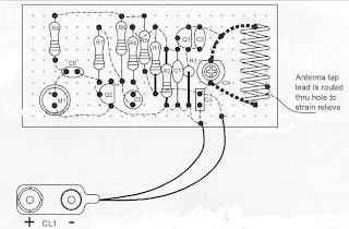
Long range FM voice Transmitter circuit
This circuit shows how to build a super-sensitive, mini-powered FM transmitter consisting of a RF (radio Frequency) oscillator section interfaced with a high sensitivity, wide pass-band audio amplifier and capacitance mike with a built-in FET (Field Effect Transistor) that modulates the base of the RF oscillator transistor. Transistor Q1 forms a relatively stable RF oscillator whose frequency and is determined by the value of coil L1 and turning capacitor C4.
Part List :
R1_______15K
R2_______3K9
R3_______220R
R4,R5____1K
R6,R9____10K
R7_______390K
C1,C6____0.01uF
C2_______4.7pF
C3_______0.1uF
C4_______6-35pf trimmer cap
C5_______2.2uF
B1_______3V
L1_______Coil winding (see below)
Q1,Q2____PN2222
M1_______Special FET bypassed microphone
Assemble L1 :Form L1 by tightly wrapping eight turns of #16 bus wire on a #8 wood screw. Produces an eight-turn coil with an inner diameter of approximately 0.135 inches and lenght of about 0.625 inches. Insert in the proper hole and solder as shown.


Comments
Post a Comment